In the casting process, cavities that are not open and lined up with the sliding direction of the die are not feasible. Designs obtained by topology optimization often contain cavities that are not viable for casting. Transformation of such a design proposal to a manufacturable design could be extremely difficult, if not impossible. In some cases where this transformation is made, the likelihood of severely affecting the design optimality is high.
OptiStruct allows you to impose draw direction constraints so that the topology determined will allow the die to slide in a given direction. These constraints are defined using the DTPL card. Different constraints can be applied to different structural parts, specified by PSOLID IDs. There are two DRAW options available. The option 'SINGLE' assumes that a single die will be used and it slides in the given drawing direction. The bottom surface of the considered casting part is the predefined contra part for the die. The option 'SPLIT' implies that two dies splitting apart in the given draw direction will be used to cast the part described in this DTPL card. The splitting surface of the two dies is optimized during the optimization process.
It is often a requirement of certain designs that no through – holes exist. These holes can be prevented from forming in the direction of the draw through use of the ‘NO HOLE’ option. This parameter is also defined on the DTPL card. With ‘NO HOLE,’ the topology can only evolve gradually from the boundary one layer at a time, and in certain cases, it may take several iterations to remove one layer.
Available with the ‘SINGLE’ draw option is a stamping or sheet metal manufacturing constraint. This option forces the evolution of 3D shell interpretable structure from a 3D design domain. This allows the design of 2D shell or stamped parts from a 3D design domain allowing greater design flexibility. The ‘STAMP’ option is also specified on the DTPL card along with a thickness value that represents the desired thickness of the resulting shell or stamped part.
A casting may contain a non-designable region in addition to a designable region. These non-designable regions must be defined as obstacles for the casting process on the same DTPL card. This preserves the casting feasibility of the final structure.
Also note that there is a default minimum member size for use with draw direction constraints. This is determined internally to be three times the average mesh size of the relevant components. Therefore, the mesh density of the model and the target volume fraction should be chosen so that enough material is available to fill members of the default minimum size. You can specify a desired minimum member size for each design part defined by a DTPL card. This value must be larger than the default value or else it will be replaced by the default value.
The considered beam is clamped on one end and loaded with a pair of twisting forces on the free end. The finite element model is shown in Figure 1.1. The design problem is to minimize the compliance with a volume fraction constraint of 0.3. The final design without draw direction constraints is shown in Figure 1.2. The chosen draw direction is along the Z-axis. The designs with the options 'SINGLE’ and 'SPLIT' for draw direction constraint are shown in Figures 1.3 and 1.4, respectively.
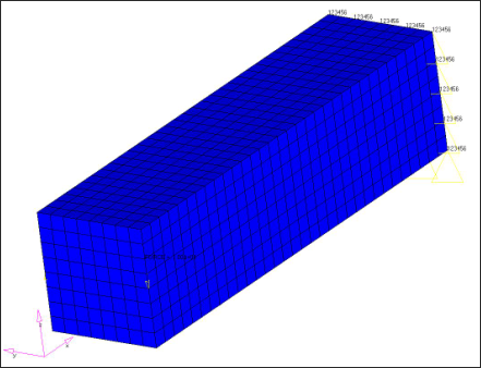
Figure 1.1: Finite element model of the beam under torsion
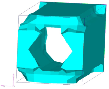
Figure 1.2: Design without draw direction manufacturing constraint
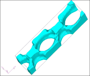
Figure 1.3: Design with draw direction Z and die option 'SINGLE'
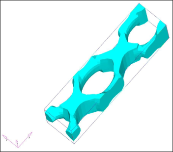
Figure 1.4: Design with draw direction Z and die option 'SPLIT'
As expected, the result without manufacturing constraints is a tube-like structure that is indeed the optimal topology for torsion load. However, this design does not permit the sliding of the die in the Z direction. The result that allows the sliding of the die for casting is not very intuitive, it forms a periodical X pattern to cross the pair of twist loads until they reach the supported end. Significantly more material at the crossing point reflects the doubled shear force at this point. Compared to an upward facing C channel solution, the cross pattern has the advantage that the stress is periodical in every X cell, thus eliminating higher order influence of the span of the beam for any solution that has system level bending action.
|
The example shown below is an engine bracket model of a car. The finite element model of the design domain is shown in Figure 2.1, in which 9046 elements are used and the design domain is shown in blue color. Six load cases were considered, which reflect the following driving and service status: 1) start; 2) backwards; 3) into a pothole; 4) out of a pothole; 5) loads from an attaching part; and 6) loads during engine transport. The final topology that allows a single die sliding upwards is shown in Figure 2.2. The design that allows two dies to slide up and down, respectively, is shown in Figure 2.3.
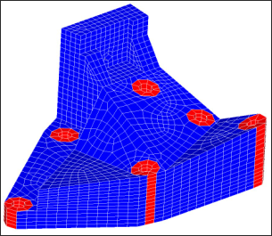
Figure 2.1: Finite element model of a engine bracket

Figure 2.2: Design with draw direction Z and die option 'SINGLE'
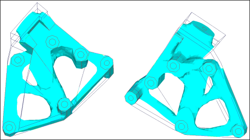
Figure 2.3: Design with draw direction Z and die option 'SPLIT'
|
In this example, a topology optimization is run on a compressor mounting bracket, and the effects of the ‘NO HOLE’ manufacturing constraint will be showcased. The finite element model is shown in Figure 3.1. Regions in red indicate non-design space and the region in blue indicates design space. Four different loading conditions were considered representing operating conditions, and the model was built up with approximately 90,000 elements. The design problem was formulated to minimize the compliance as the objective function, with a constraint on the design volume fraction.
Figure 3.2 shows the design proposal for the compressor mounting bracket without the use of the ‘NO HOLE’ manufacturing constraint. As seen in the image, the design contains through-holes.
Figure 3.3 on the other hand, shows the design proposal of the bracket with the use of the ‘NO HOLE’ constraint. In this case, the resulting design proposal does not contain any through-holes.
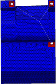
Figure 3.1: Finite element model representing the design and non-design spaces of the compressor mounting bracket
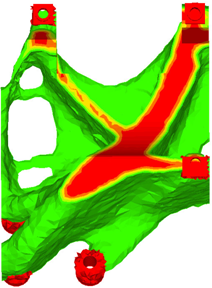
Figure 3.2: Design proposal without the ‘NO HOLE’ option
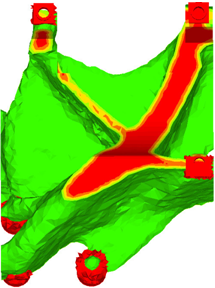
Figure 3.3: Design proposal with the ‘NO HOLE’ option
|
The bracket in this example was designed incorporating the ‘NO HOLE’ constraint along with the ‘STAMP’ constraint. The goal of the study was to generate a design proposal without any through-holes, while at the same time being interpretable as a sheet metal design. The ‘STAMP’ constraint here forces the formation of a 3D shell interpretable structure representing a sheet metal design. Four subcases representing four different loading conditions were considered and the model was comprised of approximately 20,000 elements. The optimization problem was formulated to minimize the weighted compliance (one compliance value per subcase) for a constrained design volume fraction. This essentially results in evolving the stiffest design for a given amount of material.
Figure 4.1 represents the finite element model of the design and non-design spaces of the bracket. The regions in red are the non-design regions and the region in blue is the design space.
Figure 4.2 is the design proposal without the consideration of the ‘STAMP’ and ‘NO HOLE’ manufacturing requirements. While it is possible to cast such a design, stamping such a part is not feasible.
Figures 4.3 and 4.4 showcase the design proposal after incorporating the ‘STAMP’ and ‘NO HOLE’ manufacturing constraints. The ‘NO HOLE’ constraint prevents the formation of any through-holes in the design space and helps keep a continuous shell layout, while the ‘STAMP’ constraint leads to the formation of a uniform thickness design proposal. The thickness is defined along with the ‘STAMP’ constraint and represents the desired thickness of the sheet metal part. From this proposal, it is now possible to interpret the design as a sheet metal or stamped part.
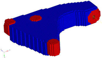
Figure 4.1: Finite element model representing the design and non-design spaces of the bracket
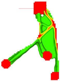
Figure 4.2: Design proposal without ‘STAMP’ and ‘NO HOLE’
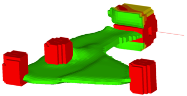
Figure 4.3: Design proposal with ‘STAMP’ and ‘NO HOLE’ (view 1)
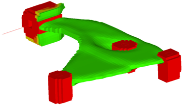
Figure 4.4: Design proposal with ‘STAMP’ and ‘NO HOLE’ (view 2)
|
See Also:
Design Variables for Topology Optimization
Multi-Model Optimization


