OptiStruct solves topological optimization problems using the density method, also known as the SIMP method in the research community.
Under topology optimization, the material density of each element should take a value of either 0 or 1, defining the element as being either void or solid, respectively. Unfortunately, optimization of a large number of discrete variables is computationally prohibitive. Therefore, representation of the material distribution problem in terms of continuous variables has to be used.
With the density method, the material density of each element is directly used as the design variable, and varies continuously between 0 and 1; these represent the state of void and solid, respectively. Intermediate values of density represent fictitious material. The stiffness of the material is assumed to be linearly dependent on the density. This material formulation is consistent with our understanding of common materials. For example, steel, which is denser than aluminum, is stronger than aluminum. Following this logic, the representation of fictitious material at intermediate densities does reflect engineering intuitions.
In general, the optimal solution of problems involves large gray areas of intermediate densities in the structural domain. Such solutions are not meaningful when you are looking for the topology of a given material, and not meaningful when considering the use of different materials within the design space. Therefore, techniques need to be introduced to penalize intermediate densities and to force the final design to be represented by densities of 0 or 1 for each element. The penalization technique used is the "power law representation of elasticity properties," which can be expressed for any solid 3D or 2D element as follows:
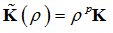
Where,  and K represent the penalized and the real stiffness matrix of an element, respectively,
  is the density and p is the penalization factor which is always greater than 1.
In a Topology Optimization run, Gravity loading (GRAV) and Rotational Force (RFORCE) are calculated with the penalized mass matrix. However, the mass response value printed to the .out file for each iteration does not consider the penalty but simply the mass times the density, because the mass matrix is penalized for gravity force calculation and if there are semi-dense elements in the model which is usually the case for non-converged iterations, the “Sum of the applied forces” or SPCFORCE values printed in the .out file will be different from their expected values (from the printed mass response). After convergence, typically the SPCFORCE and “Sum of Applied forces” will be closer to the printed mass response-based applied force calculation since the converged solution typically is more discrete and contains lower number of intermediate density elements.
In OptiStruct, the DISCRETE parameter corresponds to (p - 1). DISCRETE can be defined on the DOPTPRM bulk data entry. p usually takes a value between 2.0 and 4.0. For example, compared to the non-penalized formulation (which is equivalent to p=1) at  =0.3, p=2 reduces the stiffness of the element from 0.3 to 0.09 times the stiffness of the fully dense element. The default DISCRETE is 1.0 for shell dominant structures, and 2.0 for solids dominant structures with member size control and no manufacturing constraints (the dominance is defined by the proportion of number of elements). An additional parameter, DISCRT1D, can also be defined on the DOPTPRM bulk data entry. DISCRT1D allows 1D elements to use a different penalization to 2D or 3D elements.
For non-solid dominant models, when minimum member size control is used, the penalty starts at 2 and is increased to 3 for the second and third iterative phases. This is done in order to achieve a more discrete solution. For other manufacturing constraints such as draw direction, extrustion, pattern repetition, and pattern grouping, the penalty starts at 2 and increases to 3 and 4 for the second and third iterative phases, respectively. Obviously, due to the existence of semi-dense elements, the analysis results may change dramatically when the design process enters a new phase using a different penalization factor.
Model
|
DOPTPRM, DISCRETE
|
Penalty
|
Shell-dominant structure
|
1.0
|
2.0
|
Shell-dominant structure + member size control only
|
1.0
|
1st Phase – 2.0
2nd Phase – 3.0
3rd Phase – 3.0
|
Shell-dominant structure + other manufacturing constraints
|
1.0
|
1st Phase – 2.0
2nd Phase – 3.0
3rd Phase – 4.0
|
Solid-dominant structure
|
1.0
|
2.0
|
Solid-dominant structure + member size control only
|
2.0
|
1st Phase – 3.0
2nd Phase – 4.0
3rd Phase – 4.0
|
Solid-dominant structure + other manufacturing constraints
|
1.0
|
1st Phase – 2.0
2nd Phase – 3.0
3rd Phase – 4.0
|
Figure: Default DISCRETE and Penalty values for Topology Optimization
Three types of finite elements can be defined as topology design elements in OptiStruct: Solid elements, shell elements, and 1D elements (including ROD, BAR/BEAM, BUSH, and WELD elements).
See Also:
Topology Optimization
Multi-Model Optimization


