Pattern grouping is a feature that allows you to define a single part of the domain that should be designed in a certain pattern.
Planar Symmetry
It is often desirable to produce a design that has symmetry. Unfortunately, even if the design space and boundary conditions are symmetric, conventional topology optimization methods do not guarantee a perfectly symmetric design.
By using symmetry constraints in topology optimization, symmetric designs can be attained regardless of the initial mesh, boundary conditions, or loads. Symmetry can be enforced across one plane, two orthogonal planes, or three orthogonal planes. A symmetric mesh is not necessary, as OptiStruct will create variables that are very close to identical across the plane(s) of symmetry.
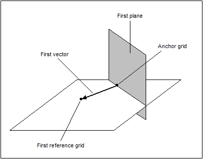
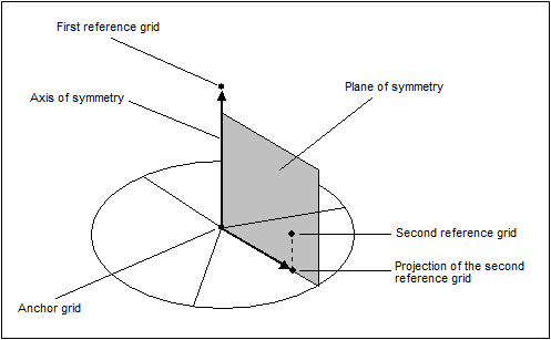
To define symmetry across one plane, it is necessary to provide an anchor grid and a reference grid. The first vector runs from the anchor grid to the reference grid. The plane of symmetry is normal to that vector and passes through the anchor grid.
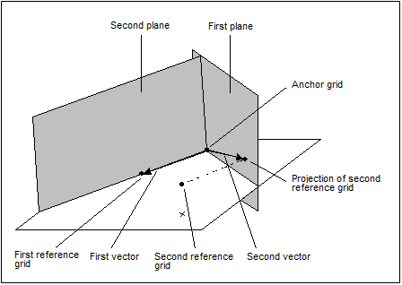
To define symmetry across two planes, a second reference grid needs to be provided. The second vector runs from the anchor grid to the projection of the second reference grid onto the first plane of symmetry. The second plane of symmetry is normal to that vector and passes through the anchor grid.
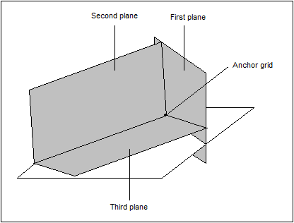
To define symmetry across three planes, no additional information is required, other than to indicate that a third plane of symmetry is to be used. The third plane of symmetry is perpendicular to the first two planes of symmetry, and also passes through the anchor grid.
Uniform Element Density
Pattern grouping also provides the possibility to request a uniform element density throughout selected components.
This pattern group ensures that all elements of selected components maintain the same element density with respect to one another.
Cyclical Symmetry
Cyclical symmetry can also be defined through the use of pattern grouping.
With cyclical pattern grouping, the design is repeated about a central axis a number of times determined by you. Furthermore, the cyclical repetitions can be symmetric within themselves. If that option is selected, OptiStruct will force each wedge to be symmetric about its centerline.
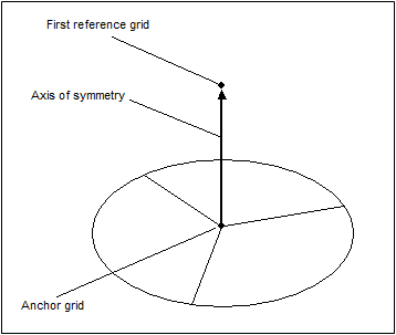
To define cyclical symmetry, it is necessary to provide an anchor grid and a reference grid. The axis of symmetry runs from the anchor grid to the reference grid. It is also necessary to specify the number of cycles; the repetition angle will be automatically computed.
To add planar symmetry within each wedge, a second reference grid needs to be provided. The plane of symmetry is determined by the anchor grid and the two reference grids.
Pattern Grouping with Draw Direction Constraints
Draw direction constraints can be combined with pattern grouping.
As illustrated below for one-plane symmetry, the sense of the vector defining the symmetry also determines the primary side of the design space to which the draw direction applies. The draw direction for the secondary side of the design space is automatically computed.
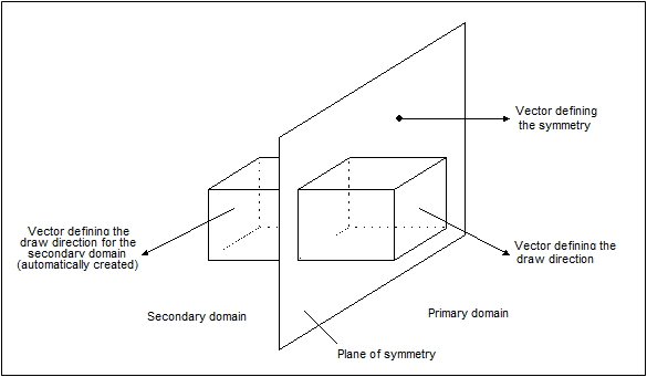
The same reasoning applies for two-plane and three-plane symmetries, as well as for cyclical symmetry.
Caution should be used in order to achieve manufacturable designs. With cyclical symmetry, for instance, the draw direction should be parallel to the axis of symmetry.
Pattern Grouping with Extrusion Constraints
Currently extrusion constraints cannot be used simultaneously with pattern grouping.
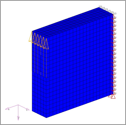
A solid block of material is used in this example. The grids located on the rear of the block (in the YZ plane) are fully constrained. Axial loading is applied to the block's upper edge in the direction of the negative Y-axis. The objective is to minimize the compliance with a constraint on the volume fraction. Single-die draw direction constraints are applied in the direction of the positive Z-axis.
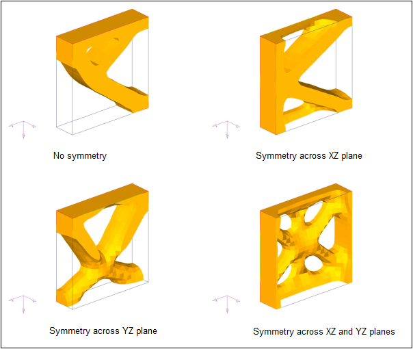
The figures below illustrate the results obtained for various symmetry combinations. As the loading is not symmetric with respect to the XY and YZ planes, the design is not symmetrical about these planes when symmetry constraints are not specified. Enforcing symmetry conditions about the XY or YZ planes yields significantly different results.
|
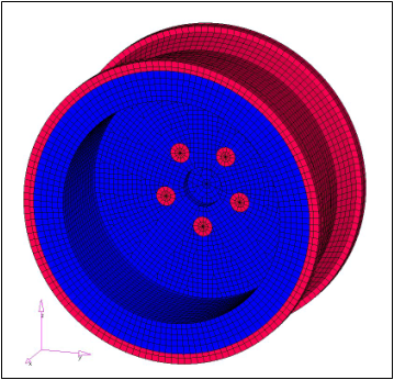
Here, solid elements are used to model a car wheel. The outer layers as well as the bolts are non-designable. Twenty load cases are considered. The objective is to minimize the weighted compliance with a constraint on the volume fraction. Split-die draw direction constraints are applied in the direction of the X-axis. Cyclical pattern grouping is defined with planar symmetry within each cycle.
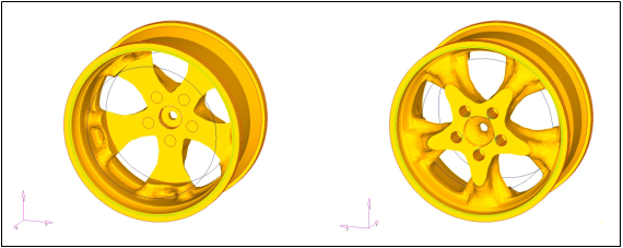
As the results show, a clean and reasonably manufacturable design is achieved. Cyclical symmetry is obtained even though the loading is not symmetric.
|
See Also:
Multi-Model Optimization


