HyperWorks Solvers

/DTPL

/DTPL

Previous topic Next topic Expand/collapse all hidden text  

/DTPL

Previous topic Next topic JavaScript is required for expanding text JavaScript is required for the print function  

Optimization Keyword

/DTPLDesign Variable for Topology Optimization

Description

Defines parameters for the generation of topology design variables.

Format

(1)

(2)

(3)

(4)

(5)

(6)

(7)

(8)

(9)

(10)

/DTPL/dtpl_ID

title

grpart_ID

TMIN

STRESS

MEMBSIZ

PATRN

PATREP

EXTR

MESH

DRAW

MMOCID


TMIN =0/1, if TMIN=1., read thickness definition: T0

(1)

(2)

(3)

(4)

(5)

(6)

(7)

(8)

(9)

(10)

T0


STRESS=0/1, if STRESS =1, read stress constraint definition: MAXSTRS

(1)

(2)

(3)

(4)

(5)

(6)

(7)

(8)

(9)

(10)

MAXSTRS


MEMBSIZ=0/1, if MEMBSIZ =1, read member size constraint definition:

(1)

(2)

(3)

(4)

(5)

(6)

(7)

(8)

(9)

(10)

MINDIM

MAXDIM

MINGAP


PATRN=0/1, if PATRN =1, read pattern grouping constraint definition (Comment 2):

(1)

(2)

(3)

(4)

(5)

(6)

(7)

(8)

(9)

(10)

TYP

AID

XA

YA

ZA


FID

XF

YF

ZF


UCYC

SID

XS

YS

ZS


PATREP =0/1/2,

If PATREP =1, read MASTER definitions for pattern repetition constraint (Comment 3):

(1)

(2)

(3)

(4)

(5)

(6)

(7)

(8)

(9)

(10)

ptrepCID


CAID

XCA

YCA

ZCA


CFID

XCF

YCF

ZCF


CSID

XCS

YCS

ZCS


CTID

XCT

YCT

ZCT


If PATREP =2, read SLAVE definitions for pattern repetition constraint (Comment 3):

(1)

(2)

(3)

(4)

(5)

(6)

(7)

(8)

(9)

(10)

masterID

SX

SY

SZ


ptrepCID


CAID

XCA

YCA

ZCA


CFID

XCF

YCF

ZCF


CSID

XCS

YCS

ZCS


CTID

XCT

YCT

ZCT


EXTRU=0/1, if EXTRU =1, read the extrusion constraint definition (Comment 4):

(1)

(2)

(3)

(4)

(5)

(6)

(7)

(8)

(9)

(10)

ETYP

extrGRN1

extrGRN2


MESH=0/1, if MESH =1, read mesh type definition:

(1)

(2)

(3)

(4)

(5)

(6)

(7)

(8)

(9)

(10)

MTYP


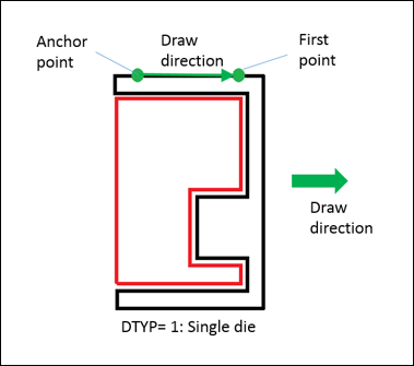
DRAW =0/1, if DRAW=1, read draw direction constraint definition (Comment 5):

(1)

(2)

(3)

(4)

(5)

(6)

(7)

(8)

(9)

(10)

DTYP

DAID

XDA

YDA

ZDA


DFID

XDF

YDF

ZDF


ogrpart

NOHOLE

TSTAMP


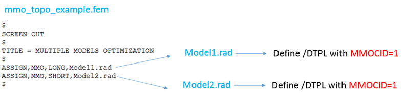
MMOCID =0/1, if MMOCID=1, read skew identifier for mapping the design domains in Multi Model Optimization:

(1)

(2)

(3)

(4)

(5)

(6)

(7)

(8)

(9)

(10)

MCID


hmtoggle_plus1Flag Definition

Field

Contents

dtpl_ID

Topology design variable identifier.

(Integer > 0)

title

Title.

(Character, maximum 100 characters)

grpart_ID

Part group identifier defining the design space.

(Integer > 0)

TMIN

Indicates if minimum thickness definition is defined.

Default = 0  (Integer)

= 0: No

= 1: Yes

T0

Minimum thickness

(Real > 0.0)

STRESS

Indicates if the von Mises stress constraint is to be defined.

(Integer)

= 0: No

= 1: Yes

MAXSTRS

Upper bound of the constraint on von Mises stress.

No default (Real > 0.0)

MEMBSIZ

Active member size control flag.

(Integer > 0)

= 0: No

= 1: Yes

MINDIM

Specifies the minimum diameter of members formed. This field can be used to eliminate small members. It also eliminates checkerboard results.

Default = No Minimum Member Size Control (Real > 0.0)

MAXDIM

Specifies the maximum diameter of members formed. This field can be used to prevent the formation of large members. It can only be used in conjunction with MINDIM.

Default = No Maximum Member Size Control (Real > 0.0)

MINGAP

Defines the minimum spacing between structural members formed. This command can only be used in conjunction with MAXDIM.

Default = blank (Real > MAXDIM)

PATRN

Active pattern grouping flag. See Comment 2.

(Integer)

= 0: No

= 1: Yes

TYP

Pattern grouping type requested.

Default = No pattern grouping (Integer)

= 1: 1-plane symmetry

= 2: 2-plane symmetry

= 3: 3-plane symmetry

= 10: Cyclic

= 11: Cyclic with symmetry

AID

Anchor node identifier for variable pattern grouping definition..

(Integer > 0 or blank)

If blank, the XA, YA, and ZA fields should not be blank.

XA, YA, ZA

Coordinates of the pattern grouping anchor point.

(Real or blank)

If blank, AID should not be blank.

FID

Node identifier used to define the direction of the first vector for variable pattern grouping.

(Integer > 0 or blank)

If blank, the XF, YF, and ZF fields should not be blank.

XF, YF, ZF

Components of the first vector used to define pattern grouping.

(Real or blank)

If blank, FID should not be blank.

UCYC

Number of cyclic repetitions for cyclical symmetry. This field defines the number of radial "wedges" for cyclical symmetry. The angle of each wedge is computed as 360.0/UCYC.

Default = blank (Integer > 0 or blank)

SID

Node identifier of the second point for pattern grouping definition.

(Integer or blank)

If blank, the XS, YS, and ZS fields should not be blank.

XS, YS, ZS

Coordinates of the second point for pattern grouping definition.

(Real or blank)

If blank, SID should not be blank.

PATREP

Indicates whether pattern repetition is defined and the type of pattern repetition. See Comment 3.

(Integer)

= 0: no pattern repetition

= 1: pattern repetition is defined, and this design variable is master

= 2: pattern repetition is defined, and this design variable is slave

masterID

Master /DTPL identifier for pattern definition.

(Integer > 0) Only needed if PATREP =2.

SX, SY, SZ

Scale factors for pattern repetition in X, Y, and Z directions respectively.

Default = 1.0 (Real > 0.0)

ptrepCID

Skew coordinate system identifier that defines the pattern repetition coordinate system.

Default = 0 (Integer > 0)

CAID

Node identifier of the anchor point for the definition of a pattern repetition coordinate system.

(Integer > 0 or blank)

If blank, the XCA, YCA, and ZCA fields should not be blank.

XCA, YCA, ZCA

Coordinates of anchor point for the definition of a pattern repetition coordinate system.

(Real or blank)

If blank, CAID should not be blank.

CFID

Node identifier of the first point for the definition of a pattern repetition coordinate system.

(Integer > 0 or blank)

If blank, the XCF, YCF, and ZCF fields should not be blank.

XCF, YCF, ZCF

Coordinates of the first point for the definition of a pattern repetition coordinate system definition.

(Real or blank)

If blank, CFID should not be blank.

CSID

Node identifier of the second point for the definition of a pattern repetition coordinate system.

(Integer > 0 or blank)

If blank, the XCS, YCS, and ZCS fields should not be blank.

XCS, YCS, ZCS

Coordinates of the second point for the definition of a pattern repetition coordinate system.

(Real or blank)

If blank, CSID should not be blank.

CTID

Node identifier of the third point for the definition of a pattern repetition coordinate system.

(Integer > 0 or blank)

If blank, the XCT, YCT, and ZCT fields should not be blank.

XCT, YCT, ZCT

Coordinates of the third point for the definition of a pattern repetition coordinate system.

(Real or blank)

If blank, CTID should not be blank.

EXTRU

Active extrusion constraint flag. See Comment 4.

(Integer)

= 0: Not active

= 1: Active

ETYP

Extrusion constraint type to be used.

(Integer)

= 0: NOTWIST. Indicates that the cross-section cannot twist around the neutral axis, in which case only one path needs to be defined.

= 1: TWIST. Indicates that the cross-section can twist around the neutral axis, in which case two paths need to be defined.

extrGRN1

Node group identifier that defines the primary extrusion path.

(Integer > 0)

extrGRN2

Node group identifier that defines the secondary extrusion path.

(Integer > 0 or blank)

If this field is blank, the secondary extrusion path is not specified.

This is only required when ETYP=1 (TWIST) is defined.

MESH

Indicates that mesh type information is to follow.

(Integer)

= 0: Not active

= 1: Active

MTYP

Indicates that the mesh conforms to certain rules for which the optimizer is tuned. Currently, only the ALIGN option is available. ALIGN indicates when manufacturing constraints are active, the mesh is aligned with the draw direction or extrusion path.

(Integer)

= 1: ALIGN

DRAW

Active draw/casting direction constraint flag. See Comment 5.

(Integer)

= 0: Not active

= 1: Active

MMOCID

Skew identifier flag for mapping the design domains in Multi-Model Optimization.

= 0: Not active

= 1: Active

DTYP

Draw direction constraint type to be used.

(Integer)

= 1: Single die

DAID

Node identifier used for the definition of a draw direction anchor point.

(Integer > 0 or blank)

If blank, the XDA, YDA, and ZDA fields should not be blank.

XDA, YDA, ZDA

Coordinates of the draw direction anchor point.

(Real or blank)

If XDA, YDA, and ZDA are blank, DAID should not be blank.

DFID

Node identifier for the definition of a draw direction point. The vector is defined from the anchor point to this point.

(Integer > 0 or blank)

If blank, the XDF, YDF, and ZDF fields should not be blank.

XDF, YDF, ZDF

Direction of the vector for draw direction definition. These fields define a point. The vector is defined from the anchor point to this point.

(Real or blank)

If XDF, YDF, and ZDF are blanks, DFID should not be blank.

ogrpart

Part group identifier of non-designable parts, whose interaction with designable parts needs to be considered with regard to the defined draw direction. OBST stands for obstacle.

Only recognized if DRAW flag is also present on same DTPL card.

(Integer > 0 or blank)

> 0: part group identifier of non-designable parts

blank: this definition is not active.

NOHOLD

Flag preventing the formation of through-holes in the draw direction. Note that it does not prevent holes perpendicular to the draw direction. The assumed minimum thickness in the draw direction is twice the average mesh size.

(Integer)

= 0: control off

= 1: control on

TSTAMP

Defines the thickness of the 3D shell structure into which the design is forced to evolve into. The recommended minimum thickness is three times the average mesh size.

(Real > 0.0 or blank)

If blank, the design is not forced to evolve into a 3D shell structure.

MCID

Skew identifier used for mapping the design domains in Multi-Model Optimization.

hmtoggle_plus1Example

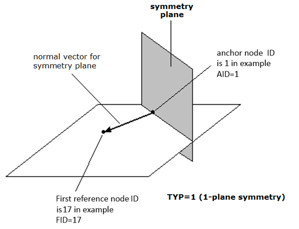
Pattern is activated with TYP=1 (1-plane symmetry)


dtpl_example

Pattern is activated and use TYP=1 (1-plane symmetry).

/DTPL/1

grpart 6 for topology optimization

### PATRN=1: active pattern

### TYP= 1: 1-plane symmetry

### AID=1: anchor node ID for variable pattern is 1

### FID=17: Node ID 17 used to define the direction of the first vector

#---1----|----2----|----3----|----4----|----5----|----6----|----7----|----8----|----9----|---10----|

#grpart_ID      TMIN    STRESS   MEMBSIZ     PATRN    PATREP      EXTR      MESH      DRAW

         6                                       1

#      TYP       AID                  XA                  YA                  ZA

         1         1

#                FID                  XF                  YF                  ZF

                  17

#     UCYC       SID                  XS                  YS                  ZS


#---1----|----2----|----3----|----4----|----5----|----6----|----7----|----8----|----9----|---10----|

hmtoggle_plus1Example (MMODIC)

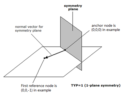
Draw and MMOCID is activated with TYP=1 (1-plane symmetry)

dtpl_example_mmocid

dtpl_example_mmo_topo


#---1----|----2----|----3----|----4----|----5----|----6----|----7----|----8----|----9----|---10----|

/DTPL/1

grpart 1 for topology optimization

### MEMBSIZ=1: active member size control

### DRAW=1: active draw/casting direction constraint

### MMOCID=1: active Skew identifier flag for mapping the design domains in Multi-Model Optimization

### minimum diameter of members MINDIM=40 and maximum diameter of members MAXDIM=80

### TYP= 1: 1-plane symmetry

### Normal vector is from Anchor node (XA,YA,ZA) to First node (XF,YF,ZF)

### MCID=1: Skew identifier 1 used for mapping the design domains in Multi-Model Optimization

#---1----|----2----|----3----|----4----|----5----|----6----|----7----|----8----|----9----|---10----|

#grpart_ID      TMIN    STRESS   MEMBSIZ     PATRN    PATREP      EXTR      MESH      DRAW    MMOCID

         1                             1                                                 1         1

#             MINDIM              MAXDIM               MINGAP

                  40                  80

#      TYP       AID                  XA                  YA                  ZA

         1                             0                   0                   0

#                FID                  XF                  YF                  ZF

                                       0                   0                  -1

#     UCYC       SID                  XS                  YS


#     MCID

         1

#---1----|----2----|----3----|----4----|----5----|----6----|----7----|----8----|----9----|---10----|

hmtoggle_plus1Comments
1.For PATRN=1 (active pattern), there are five pattern grouping options:

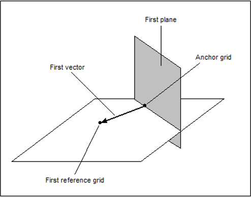
1-plane symmetry (TYP = 1)

This type of pattern grouping requires the anchor point and first point to be defined. A vector from the anchor point to the first point is normal to the plane of symmetry.

dtpl_1_plane

2-plane symmetry (TYP = 2)

This type of pattern grouping requires the anchor point, first point, and second point to be defined. A vector from the anchor point to the first point is normal to the first plane of symmetry. The second point is projected normally onto the first plane of symmetry. A vector from the anchor point to this projected point is normal to the second plane of symmetry.

dtpl_2_plane

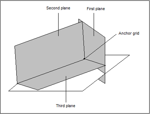
3-plane symmetry (TYP = 3)

This type of pattern grouping requires the anchor point, first point, and second point to be defined. A vector from the anchor point to the first point is normal to the first plane of symmetry. The second point is projected normally onto the first plane of symmetry. A vector from the anchor point to this projected point is normal to the second plane of symmetry. The third plane of symmetry is orthogonal to both the first and second planes of symmetry, passing through the anchor point.

dtpl_3_plane

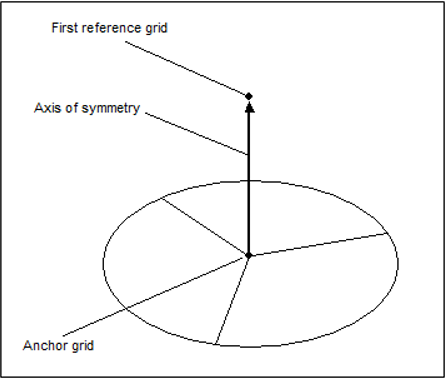
Cyclic (TYP = 10)

This type of pattern grouping requires the anchor point, first point, and number of cyclical repetitions to be defined. A vector from the anchor point to the first point defines the axis of symmetry.

dtpl_cyclic_10

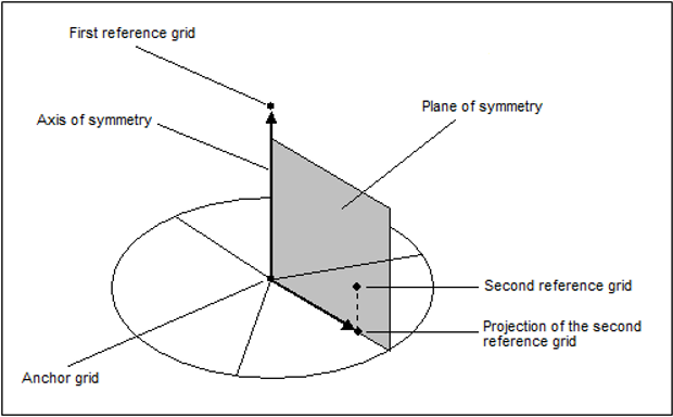
Cyclic with symmetry (TYP = 11)

This type of pattern grouping requires the anchor point, first point, second point, and number of cyclical repetitions to be defined. A vector from the anchor point to the first point defines the axis of symmetry. The anchor point, first point, and second point all lay on a plane of symmetry. A plane of symmetry lies at the center of each cyclical repetition.

dtpl_cyclic

For a more detailed description, refer to Pattern Grouping contained within the User's Guide Manufacturability for Topology Optimization section.

2.PATREP =1, read MASTER definitions for pattern repetition constraint.

PATREP =2, read SLAVE definitions for pattern repetition constraint.

For a more detailed description, refer to Pattern Repetition for Topology Optimization.

3.EXTRU =1, read the extrusion constraint definition. There are two types of extrusion constraints: ETYP=0 (non-twisted cross-section) and ETYP=1 (twisted cross-section).

dtpl_extru

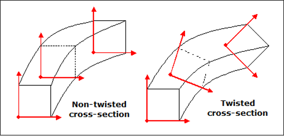
For a more detailed description, refer to Extrusion Constraints for Topology Optimization.

4.DRAW =1, read draw direction constraint definition. The type of draw direction that could be used is single die (DTYP=1).

dtpl_draw

For a more detailed description, refer to Draw Direction Constraints for Topology Optimization.

5.This entry is represented as an optimization design variable in HyperMesh and HyperCrash.

See Also:

Design Optimization

DTPL