|
»Click here to display Table of Contents«
|

DSIZE |

|

|

|

|
|
DSIZE |
|
|
|

|
|
»Click here to display Table of Contents«
|
DSIZE |
|
|
|
|
|
DSIZE |
|
|
|
|
Bulk Data Entry
DSIZE – Design Variable for Free-Size Optimization
Description
DSIZE defines parameters for the generation of free-size design variables.
Format
(1) |
(2) |
(3) |
(4) |
(5) |
(6) |
(7) |
(8) |
(9) |
(10) |
DSIZE |
ID |
PTYPE |
PID1 |
PID2 |
PID3 |
PID4 |
PID5 |
PID6 |
|
|
|
PID7 |
… |
… |
… |
… |
… |
… |
|
Optional continuation lines for thickness definition:
(1) |
(2) |
(3) |
(4) |
(5) |
(6) |
(7) |
(8) |
(9) |
(10) |
|
THICK |
T0 |
T1 |
TG |
TGX |
TGY |
TGZ |
|
|
Optional continuation lines for stress constraint definition:
(1) |
(2) |
(3) |
(4) |
(5) |
(6) |
(7) |
(8) |
(9) |
(10) |
|
STRESS |
UBOUND |
|
|
|
|
|
|
|
Optional continuation lines for member size constraint definition:
(1) |
(2) |
(3) |
(4) |
(5) |
(6) |
(7) |
(8) |
(9) |
(10) |
|
MEMBSIZ |
MINDIM |
|
|
|
|
|
|
|
Optional continuation lines for composite manufacturing constraints definition:
(1) |
(2) |
(3) |
(4) |
(5) |
(6) |
(7) |
(8) |
(9) |
(10) |
|---|---|---|---|---|---|---|---|---|---|
+ |
COMP |
LAMTHK |
LTMIN |
LTMAX |
LTSET |
LTEXC |
|
|
|
+ |
COMP |
PLYTHK |
PTGRP |
PTMIN |
PTMAX |
PTOPT |
PTSET |
PTEXC |
|
+ |
COMP |
PLYPCT |
PPGRP |
PPMIN |
PPMAX |
PPOPT |
PPSET |
PPEXC |
|
+ |
COMP |
PLYMAN |
PMGRP |
PMMAN |
|
PMOPT |
PMSET |
PMEXC |
|
+ |
COMP |
BALANCE |
BGRP1 |
BGRP2 |
|
BOPT |
|
|
|
+ |
COMP |
CONST |
CGRP |
CTHICK |
|
COPT |
|
|
|
+ |
COMP |
PLYDRP |
PDGRIP |
PDTYP |
PDMAX |
PDOPT |
PDSET |
PDEXC |
|
+ |
|
|
PDDEF |
PDX |
PDY |
PDZ |
|
|
|
Optional continuation lines for pattern grouping constraint definition:
(1) |
(2) |
(3) |
(4) |
(5) |
(6) |
(7) |
(8) |
(9) |
(10) |
|
PATRN |
TYP |
AID/XA |
YA |
ZA |
FID/XF |
YF |
ZF |
|
|
|
UCYC |
SID/XS |
YS |
ZS |
|
|
|
|
Optional continuation lines for "Master" definition for pattern repetition constraint:
(1) |
(2) |
(3) |
(4) |
(5) |
(6) |
(7) |
(8) |
(9) |
(10) |
|
MASTER |
|
|
|
|
|
|
|
|
|
COORD |
CID |
CAID/XCA |
YCA |
ZCA |
CFID/XCF |
YCF |
ZCF |
|
|
|
|
CSID/XCS |
YCS |
ZCS |
CTID/XCT |
YCT |
ZCT |
|
Optional continuation lines for "Slave" definition for pattern repetition constraint:
(1) |
(2) |
(3) |
(4) |
(5) |
(6) |
(7) |
(8) |
(9) |
(10) |
|
SLAVE |
DSIZE_ID |
SX |
SY |
SZ |
|
|
|
|
|
COORD |
CID |
CAID/XCA |
YCA |
ZCA |
CFID/XCF |
YCF |
ZCF |
|
|
|
|
CSID/XCS |
YCS |
ZCS |
CTID/XCT |
YCT |
ZCT |
|
Optional continuation lines for fatigue constraint definition:
(1) |
(2) |
(3) |
(4) |
(5) |
(6) |
(7) |
(8) |
(9) |
(10) |
|
FATIGUE |
FTYPE |
FBOUND |
|
|
|
|
|
|
Optional continuation lines for zone based free-sizing definition:
(1) |
(2) |
(3) |
(4) |
(5) |
(6) |
(7) |
(8) |
(9) |
(10) |
|
GROUP |
|
EG1 |
EG2 |
EG3 |
EG4 |
EG5 |
EG6 |
|
|
|
EG7 |
EG8 |
EG9 |
… |
… |
… |
… |
|
Alternate continuation line for zone based free-sizing definition (Alternate Format):
(1) |
(2) |
(3) |
(4) |
(5) |
(6) |
(7) |
(8) |
(9) |
(10) |
|
GROUP |
|
EG1 |
THRU |
EG2 |
|
|
|
|
Optional continuation line for tape laying based free-sizing definition:
(1) |
(2) |
(3) |
(4) |
(5) |
(6) |
(7) |
(8) |
(9) |
(10) |
|
TAPE |
LTAPE |
WTAPE |
OFFSET |
|
|
|
|
|
Field |
Contents |
|---|---|
ID |
Each DSIZE card must have a unique ID. No default (Integer > 0) |
PTYPE |
Property type for which DSIZE card is defined. No default (PCOMP, PCOMPG, PSHELL, or STACK) |
PID# |
Property identification numbers. List of PTYPE properties for which this DSIZE card is defined. No default (Integer > 0) |
THICK |
Indicates that minimum and possibly maximum thickness value are to follow. |
T0 |
Minimum thickness. For PTYPE = PSHELL, this refers to the minimum thickness of the shell. If a value is not entered for T0, the T0 value on the PSHELL card is used. If T0 is not defined on the PSHELL card, then T0=0.0 is assumed. This option does not apply for PTYPE = PCOMP, PCOMPG, or STACK. Default = blank (Real > 0.0) |
T1 |
Maximum thickness. For PTYPE = PSHELL, this refers to the maximum thickness of the shell. If a value is not entered for T1, the T value on the PSHELL card is used. This option does not apply for PTYPE = PCOMP, PCOMPG, or STACK. Default = blank (Real > T0) |
TG |
Specifies the maximum thickness gradient. Default = blank (Real > 0.0) |
TGX, TGY, TGZ |
Defines a vector that specifies the thickness gradient direction (optional). Default = blank (Real) |
STRESS |
Indicates that von Mises stress constraints are active and that an upper bound value for the stress is to follow (Comment 4). |
UBOUND |
Upper bound constraint on von Mises stress. No default (Real > 0.0) |
MEMBSIZ |
Indicates that member size control is active for the properties listed. Indicates that MINDIM is to follow. |
MINDIM |
Specifies the minimum diameter of members formed. This command is used to eliminate small members. It also eliminates checkerboard results (Comment 3). Default = No minimum member size control (Real > 0.0) |
COMP |
Indicates that composite manufacturing constraints are applied. Indicates that information about manufacturing constraints is to follow (Comment 5). |
LAMTHK |
Indicates that laminate thickness constraints are applied. Multiple LAMTHK constraints are allowed (Comment 5). |
LTMIN |
Minimum laminate thickness for the LAMTHK constraint. Default = blank (Real > 0.0) |
LTMAX |
Maximum laminate thickness for the LAMTHK constraint. Default = blank (Real > 0.0 and > LTMIN) |
LTSET |
Set ID of elements to which the LAMTHK constraint is applied. |
LTEXC |
Exclusion flag indicating that certain plies are excluded from the LAMTHK constraint. The following options are supported: NONE: Plies are not excluded. |
PLYTHK |
Indicates that ply thickness constraints are applied. Multiple PLYTHK constraints are allowed. |
PTGRP |
Ply orientation in degrees, ply sets or ply IDs, to which the PLYTHK constraint is applied, depending on the PTOPT selection. No default (Real or Integer) |
PTMIN |
Minimum thickness for the PLYTHK constraint. Default = blank (Real > 0.0) |
PTMAX |
Maximum thickness for the PLYTHK constraint. Default = blank (Real > 0.0 and > PTMIN) |
PTOPT |
Ply selection options for the PLYTHK constraint. Plies can be selected based on the following: BYANG: Orientation (Default) |
PTSET |
Set ID of elements to which the PLYTHK constraint is applied. |
PTEXC |
Exclusion flag indicating that certain plies are excluded from the PLYTHK constraint. The following options are supported: NONE: Plies are not excluded. |
PLYPCT |
Indicates that ply thickness percentage constraints are applied. Multiple PLYPCT constraints are allowed. |
PPGRP |
Ply orientation in degrees, ply sets or ply IDs, to which the PLYPCT constraint is applied, depending on the PPOPT selection. No default (Real or Integer) |
PPMIN |
Minimum percentage thickness for the PLYPCT constraint. Default = blank (Real > 0.0 and < 1.0) |
PPMAX |
Maximum percentage thickness for the PLYPCT constraint. Default = blank (Real > 0.0, < 1.0 and > PPMIN) |
PPOPT |
Ply selection options for the PLYPCT constraint. Plies can be selected based on the following: BYANG: Orientation (Default) |
PPSET |
Set ID of elements to which the PLYPCT constraint is applied. |
PPEXC |
Exclusion flag indicating that certain plies are excluded from the PLYPCT constraint. The following options are supported: NONE: Plies are not excluded. |
PLYMAN |
Indicates that manufacturable ply thickness constraints are applied. Multiple PLYMAN constraints are allowed. |
PMGRP |
Ply orientation in degrees, ply sets or ply IDs, to which the PLYMAN constraint is applied, depending on the PMOPT selection. No default (Real or Integer) |
PMMAN |
Manufacturable ply thickness (Comment 6). Default = blank (Real > 0.0) |
PMOPT |
Ply selection options for the PLYMAN constraint. Plies can be selected based on the following: BYANG: Orientation (Default) |
PMSET |
Set ID of elements to which the PLYMAN constraint is applied. |
PMEXC |
Exclusion flag indicating that certain plies are excluded from the PLYMAN constraint. The following options are supported: NONE: Plies are not excluded. |
BALANCE |
Indicates that a balancing constraint is applied. Multiple BALANCE constraints are allowed. |
BGRP1 |
First ply orientation in degrees, ply sets or ply IDs, to which the BALANCE constraint is applied, depending on the BOPT selection. No default (Real or Integer) |
BGRP2 |
Second ply orientation in degrees, ply sets or ply IDs, to which the BALANCE constraint is applied, depending on the BOPT selection. No default (Real or Integer) |
BOPT |
Ply selection options for the BALANCE constraint. Plies can be selected based on the following: BYANG: Orientation (Default) |
CONST |
Indicates that a constant thickness constraint is applied. Multiple CONST constraints are allowed. |
CGRP |
Ply orientation in degrees, ply sets or ply IDs, to which the CONST constraint is applied, depending on the COPT selection. No default (Real or Integer) |
CTHICK |
Constant ply thickness for the CONST constraint. No default (Real > 0.0) |
COPT |
Ply selection options for the CONST constraint. Plies can be selected based on the following: BYANG: Orientation (Default) |
PLYDRP |
Indicates that ply drop-off constraints are applied. Multiple PLYDRP constraints are allowed. |
PDGRP |
Ply orientation in degrees, ply sets or ply IDs, to which the PLYDRP constraint is applied, depending on the PDOPT selection. No default (Real or Integer) |
PDTYP |
PDTYP specifies the type of the drop-off constraint as: PLYSLP (Default) (see Comment 11) |
PDMAX |
Maximum allowed drop-off for the PLYDRP constraint. No default (Real > 0) |
PDOPT |
Ply selection options for the PLYDRP constraint. Plies can be selected based on the following: BYANG: Orientation (Default) |
PDSET |
Set IDs of elements to which the PLYDRP constraint is applied. |
PDEXC |
Exclusion flag indicates that certain plies are excluded from the PLYDRP constraint. The following options are supported: NONE: Plies are not excluded. |
PDDEF |
Optional definition to fine-tune the drop-off constraint. Currently only DIRECT is available to request directional drop-off, in which case PDX, PDY and PDZ specify the drop-off direction (Comment 12). |
PDX, PDY, PDZ |
Used to specify the drop-off direction when DIRECT is input in the PDDEF field. See comment 12. |
PATRN |
Indicates that pattern grouping is active for the properties listed. Indicates that information for pattern grouping is to follow. |
TYP |
Indicates the type of pattern grouping requested (Comment 1). Default = No pattern grouping (1, 2, 3, 9, 10, 11, 20 or 21) |
AID/XA, YA, ZA |
Anchor point for pattern grouping. The point may be defined by entering a grid ID in the AID field or by entering X, Y, and Z coordinates in the XA, YA, and ZA fields. These coordinates will be in the basic coordinate system. See comment 1. Default = origin (Real in all three fields or Integer in first field) |
FID/XF, YF, ZF |
First point for pattern grouping. The point may be defined by entering a grid ID in the FID field or by entering X, Y, and Z coordinates in the XF, YF, and ZF fields. These coordinates will be in the basic coordinate system (Comment 1). No default (Real in all three fields or Integer in the first field) |
UCYC |
Number of cyclical repetitions for cyclical symmetry. This field defines the number of radial "wedges" for cyclical symmetry. The angle of each wedge is computed as 360.0/UCYC (Comment 1). Default = blank (Integer > 0 or blank) |
SID/XS, YS, ZS |
Second point for pattern grouping. The point may be defined by entering a grid ID in the SID field or by entering X, Y, and Z coordinates in the XS, YS, and ZS fields. These coordinates will be in the basic coordinate system (Comment 1). No default (Real in all three fields or Integer in first field) |
MASTER |
Indicates that this design variable may be used as a master pattern for pattern repetition (Comment 2). |
SLAVE |
Indicates that this design variable is slave to the master pattern definition referenced by the following DSIZE_ID entry (Comment 2). |
DSIZE_ID |
DSIZE identification number for a master pattern definition. No default (Integer > 0) |
SX, SY, SZ |
Scale factors for pattern repetition, in X, Y, and Z directions, respectively (Comment 2). Default = 1.0 (Real > 0.0) |
COORD |
Indicates information regarding the coordinate system for pattern repetition is to follow. This is required if either MASTER or SLAVE flags are present. |
CID |
Coordinate system ID for a rectangular coordinate system that may be used as the pattern repetition coordinate system (Comment 2). Default = 0 (Integer > 0) |
CAID/XCA, YCA, ZCA |
Anchor point for pattern repetition coordinate system. The point may be defined by entering a grid ID in the CAID field or by entering X, Y, and Z coordinates in the XCA, YCA, and ZCA fields. These coordinates will be in the basic coordinate system (Comment 2). No default (Real in all three fields or Integer in the first field) |
CFID/XCF, YCF, ZCF |
First point for pattern repetition coordinate system. The point may be defined by entering a grid ID in the CFID field or by entering X, Y, and Z coordinates in the XCF, YCF, and ZCF fields. These coordinates will be in the basic coordinate system (Comment 2). No default (Real in all three fields or Integer in the first field) |
CSID/XCS, YCS, ZCS |
Second point for pattern repetition coordinate system. The point may be defined by entering a grid ID in the CSID field or by entering X, Y, and Z coordinates in the XCS, YCS, and ZCS fields. These coordinates will be in the basic coordinate system (Comment 2). No default (Real in all three fields or Integer in the first field) |
CTID/XCT, YCT, ZCT |
Third point for pattern repetition coordinate system. The point may be defined by entering a grid ID in the CTID field or by entering X, Y, and Z coordinates in the XCT, YCT, and ZCT fields. These coordinates will be in the basic coordinate system (Comment 2). No default (Real in all three fields or Integer in the first field) |
FATIGUE |
Indicates that fatigue constraints are active and their definition is to follow. |
FTYPE |
Specifies the type of fatigue constraint; it can be DAMAGE, LIFE or FOS. |
FBOUND |
Specifies the bound value. If FTYPE is DAMAGE, FBOUND will be the upper bound of fatigue damage. If FTYPE is LIFE or FOS, FBOUND will be the lower bound of fatigue life (LIFE) or Factor of Safety (FOS), respectively. No default (Real) |
GROUP |
Specifies the definition of zone based free-sizing optimization. Indicates that element group IDs will follow. |
EG# |
Element group numbers. Element groups are created through element sets (Comment 7). No default (Integer > 0) |
THRU |
This keyword can be used in the optional alternate format to define zone based free-sizing optimization. This keyword is used for ID range definition to indicate that all ID’s between the preceding ID (EG1) and the following ID (EG2) are to be included in the set. |
TAPE |
The TAPE flag to indicate that tape laying based free-sizing definitions are active and corresponding parameters are to follow (Comments 13, 14, and 15). |
LTAPE |
Minimum Tape length No default (Real > 0.0) |
WTAPE |
Tape width No default (Real > 0.0) |
OFFSET |
Allows selecting the required option to offset contiguous patches. LOFF – Contiguous tape patches are offset along the length direction by a distance equal to half of the tape length. WOFF – Contiguous tape patches are offset along the width direction by a distance equal to half of the tape width. Default = blank (LOFF, WOFF, or blank) |
| 1. | There are currently five pattern grouping options for free-size optimization: |
1-plane symmetry (TYP = 1)
This type of pattern grouping requires that the anchor point and the first point be defined. A vector from the anchor point to the first point is normal to the plane of symmetry.
2-plane symmetry (TYP = 2)
This type of pattern grouping requires that the anchor point, first point, and second point be defined. A vector from the anchor point to the first point is normal to the first plane of symmetry. The second point is projected normally onto the first plane of symmetry. A vector from the anchor point to this projected point is normal to the second plane of symmetry.
3-plane symmetry (TYP = 3)
This type of pattern grouping requires that the anchor point, first point, and second point be defined. A vector from the anchor point to the first point is normal to the first plane of symmetry. The second point is projected normally onto the first plane of symmetry. A vector from the anchor point to this projected point is normal to the second plane of symmetry. The third plane of symmetry is orthogonal to both the first and second planes of symmetry, passing through the anchor point.
Uniform pattern grouping (TYP = 9)
This type of pattern grouping requires only the TYP field to be set equal to 9. All elements included in this DSIZE entry are automatically considered for uniform pattern grouping. All elements on this DSIZE entry are set equal to the same thickness.
Cyclic (TYP = 10)
This type of pattern grouping requires that the anchor point, first point, and number of cyclical repetitions be defined. A vector from the anchor point to the first point defines the axis of symmetry.
Cyclic with symmetry (TYP = 11)
This type of pattern grouping requires that the anchor point, first point, second point, and number of cyclical repetitions be defined. A vector from the anchor point to the first point defines the axis of symmetry. The anchor point, first point, and second point all lay on a plane of symmetry. A plane of symmetry lies at the center of each cyclical repetition.
Linear Pattern Grouping (TYP = 20)
Linear pattern grouping requires that the anchor point and first point be defined. A vector from the anchor point to the first point defines the direction in which the thickness is set to be constant. Linear pattern grouping is typically designed to handle models with minimal or no curvature in the specified vector direction (which is typically orthogonal to the rolling direction in rolling applications). For models with low curvature in the vector direction, appropriate projections to the surface are used to determine the direction on the surface. For models with high curvature in the vector direction, depending on the direction of the specified vector, the direction may become orthogonal to the surface whereby the pattern grouping direction cannot be determined. In such cases, Planar Pattern Grouping (TYP = 21) is recommended.
Planar Pattern Grouping (TYP = 21)
Planar pattern grouping requires that the anchor point and first point be defined. A vector from the anchor point to the first point is defined and thickness of the model in the various orthogonal planes to this vector is set to be constant. Planar pattern grouping is designed to handle models with high curvature in the orthogonal planes of the defined vector, and with minimal or no curvature in the direction of the defined vector. The vector defined in planar pattern grouping should typically lie in the rolling direction in rolling applications. This feature can handle large curvature in the slicing plane orthogonal to the defined vector. Planar pattern grouping cannot be used if large curvature exists in the rolling direction.
For a more detailed description, refer to Pattern Grouping for Free-Size Optimization contained within the User’s Guide section Manufacturability for Free-Size Optimization.
| 2. | Pattern repetition allows similar regions of the design domain to be linked together so as to produce similar topological layouts. This is facilitated through the definition of "Master" and "Slave" regions. A DSIZE card may only contain one MASTER or SLAVE flag. For both "Master" and "Slave" regions, a pattern repetition coordinate system is required and is described following the COORD flag. In order to facilitate reflection, the coordinate system may be a left-handed or right-handed Cartesian system. The coordinate system may be defined in one of two ways, listed here in order of precedence: |
| • | Four points are defined and these are utilized as follows to define the coordinate system (this is the only way to define a left-handed system): |
| - | A vector from the anchor point to the first point defines the x-axis. |
| - | The second point lies on the x-y plane, indicating the positive sense of the y-axis. |
| - | The third point indicates the positive sense of the z-axis. |
| • | A rectangular coordinate system and an anchor point are defined. If only an anchor point is defined, it is assumed that the basic coordinate system is to be used. |
Multiple "Slaves" may reference the same "Master."
Scale factors may be defined for "Slave" regions, allowing the "Master" layout to be adjusted.
For a more detailed description, refer to Pattern Repetition for Free-Size Optimization contained within the User’s Guide section Manufacturability for Free-Size Optimization.
| 3. | It is recommended that a MINDIM value be chosen which allows for the formation of members that are at least three elements thick. When pattern grouping constraints are active, a MINDIM value of three times the average element edge length is enforced, and user-defined values (which are smaller than this value) will be replaced by this value. |
| 4. | The von Mises stress constraints may be defined for topology and free-size optimization through the STRESS optional continuation line on the DTPL or the DSIZE card. There are a number of restrictions with this constraint: |
| • | The definition of stress constraints is limited to a single von Mises permissible stress. The phenomenon of singular topology is pronounced when different materials with different permissible stresses exist in a structure. Singular topology refers to the problem associated with the conditional nature of stress constraints that is the stress constraint of an element disappears when the element vanishes. This creates another problem in that a huge number of reduced problems exist with solutions that cannot usually be found by a gradient-based optimizer in the full design space. |
| • | Stress constraints for a partial domain of the structure are not allowed because they often create an ill-posed optimization problem since elimination of the partial domain would remove all stress constraints. Consequently, the stress constraint applies to the entire model when active, including both design and non-design regions, and stress constraint settings must be identical for all DSIZE and DTPL cards. |
| • | The capability has built-in intelligence to filter out artificial stress concentrations around point loads and point boundary conditions. Stress concentrations due to boundary geometry are also filtered to some extent as they can be improved more effectively with local shape optimization. |
| • | Due to the large number of elements with active stress constraints, no element stress report is given in the table of retained constraints in the .out file. The iterative history of the stress state of the model can be viewed in HyperView or HyperMesh. |
| • | Stress constraints do not apply to 1D elements. |
| • | Stress constraints may not be used when enforced displacements are present in the model. |
| Note: | The functionality of the STRESS continuation line to define topology and free-size stress constraints consists of many limitations. It is recommended to use DRESP1-based Stress Responses instead. Actual Stress Responses for Topology and Free-Size Optimization are available through corresponding Stress response RTYPE’s on the DRESP1 Bulk Data Entry. The Stress-NORM aggregation is internally used to calculate the Stress Responses for groups of elements in the model. |
| 5. | The following manufacturing constraints are available for composite free-sizing optimization: |
| • | Lower and upper bounds on the total thickness of the laminate (LAMTHK). |
| • | Lower and upper bounds on the thickness of a given orientation (PLYTHK). |
| • | Lower and upper bounds on the thickness percentage of a given orientation (PLYPCT). |
| • | Linking between the thicknesses of two given orientations (BALANCE). |
| • | Constant (non-designable) thickness of a given orientation (CONST). |
| • | LAMTHK, PLYTHK, PLYPCT, and PLYMAN can be applied locally to sets of elements. There can be elements that do not belong to any set. |
For a more detailed description and an example, refer to Optimization of Composite Structures in the User’s Guide.
| 6. | PLYMAN has no influence on the free-size phase, but this information will be translated into the TMANUF entry on the PLY card for the sizing phase. |
| 7. | Elements within each group will have uniform ply thicknesses. |
| 8. | The core is designable by default. It can be made non-designable through the CONST manufacturing constraint. To facilitate this, the keyword CORE can be used instead of a ply ID when BYPLY is activated. |
| 9. | The core is excluded from the LAMTHK, PLYTHK, PLYPCT and PLYMAN manufacturing constraints by default. |
| 10. | Legacy data field PTMAN (for manufacturable ply thickness) defined on the PLYTHK and PLYPCT entries is supported. However, it is now recommended to define the manufacturable ply thickness in the PMMAN field through the PLYMAN continuation line as this offers more control. |
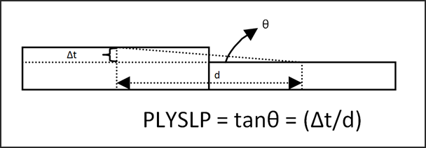
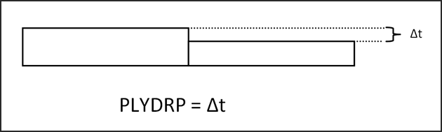
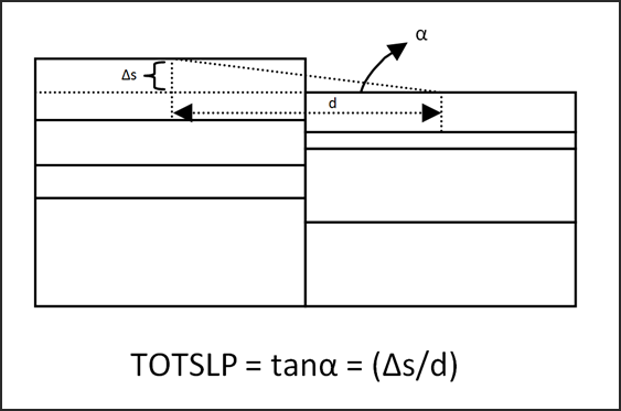
| 11. | The options for selecting the type of drop-off constraints for PDTYP are defined for a set of plies, as shown in the figures below: |
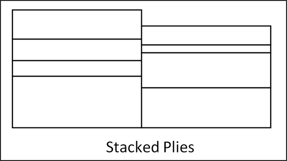
Assuming that the plies are stacked as shown above, you have the following definitions:
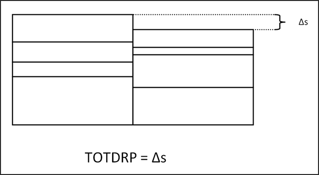
When OUTPUT,FSTOSZ is used to generate a Sizing input deck, the Ply drop-off manufacturing constraints are converted into equivalent TOTDRP constraints. Check that the estimated TOTDRP values on the DCOMP entry(s) are meaningful, or adjust the values manually, if necessary.
| 12. | The optional PDDEF definition is used to fine-tune the drop-off constraint. Currently, only the DIRECT option is available for the PDDEF field. |
Field |
Value |
|---|---|
PDDEF |
DIRECT – This option allows you to fine-tune the drop-off constraint by requesting directional drop-off. The direction of drop-off can be specified by defining a directional vector with respect to the basic coordinate system. The directional vector is defined using the PDX, PDY and PDZ values. |
PDX, PDY, PDZ |
PDX, PDY and PDZ are real numbers. These values are used to specify the drop-off direction when DIRECT is input in the PDDEF field. They specify the three components of a directional vector defined with respect to the basic coordinate system. Example: If drop-off control is required in the X-direction, then 1,0,0 can be defined in the PDX, PDY, PDZ fields, respectively. 0,1,0 can be defined for Y-direction drop-off control. |
| 13. | Other manufacturing constraints (except BALANCE) can be used along with tape laying. |
| 14. | If there are multiple plies of the same orientation, the corresponding tapes are automatically offset with respect to one another. This increases the design freedom by allowing OptiStruct to choose the optimum layout for a particular configuration. |
| 15. | Symmetry is available only at the laminate level for tape laying. Opposite orientations (for example, 45 degrees and -45 degrees) are reflections of each other, instead of being reflected across the plane of symmetry. 0 and 90 degree plies are still reflected across the plane of symmetry. |
| 16. | This card is represented as an optimization design variable in HyperMesh. |
See Also: