|
»Click here to display Table of Contents«
|

DRESP1 |

|

|

|

|
|
DRESP1 |
|
|

|

|
|
»Click here to display Table of Contents«
|
DRESP1 |
|
|
|
|
|
DRESP1 |
|
|
|
|
Bulk Data Entry
DRESP1 – Optimization Design Response
Description
A response or a set of responses that are the result of a design analysis iteration. These responses can be used as a design objective or as design constraints. For further information about the various internal responses, refer to Internal Responses in the User’s Guide.
Format
(1) |
(2) |
(3) |
(4) |
(5) |
(6) |
(7) |
(8) |
(9) |
(10) |
DRESP1 |
ID |
LABEL |
RTYPE |
PTYPE |
REGION |
ATTA |
ATTB |
ATT1 |
|
|
ATT2 |
… |
… |
… |
… |
… |
… |
… |
|
|
EXCL |
EID1 |
EID2 |
EID3 |
EID4 |
EID5 |
EID6 |
EID7 |
|
|
|
EID8 |
… |
… |
… |
|
|
|
|
|
EXTN |
RANDID |
LOWFQ |
HIGHFQ |
SCALE |
OCTAVE |
OCTOPT |
|
|
The maximum principal stress in PSHELL PID 1
or
The maximum principal stress in elements 2001-2004
The combined mass of PSHELL PID 2, 4, 7
|
Field |
Contents |
ID |
Response identification number. Each DRESP1 card must have a unique ID. No default (Integer > 0) |
LABEL |
User-defined name for the response. No default (Character) |
RTYPE |
Type of response that is defined for a particular optimization run. No default (See Responses and Attributes for DRESP1 card for full list of response types) |
PTYPE |
If a property response, then PTYPE is the property type, for example, PSHELL. It is used in conjunction with ATT1 to identify the unique property. If an element response, then PTYPE = ELEM. It is used in conjunction with ATTi to identify the element IDs. For material responses, PTYPE is MAT and ATTi are material IDs. For grid responses, PTYPE is blank and ATTi are grid IDs. (See Responses and Attributes for DRESP1 card for further information). No default (ELEM, MAT, PSHELL, PCOMP, PCOMPG, PLY, PROD, PSOLID, PELAS, PBAR, PBARL, PBEAM, PBEAML, PFBODY, PWELD, MBREQM, MBREQE, FATSEAM, or blank) |
REGION |
Region identifier. Default = blank (Integer > 0 or blank, See comment 2) |
ATTA, ATTB |
The attributes of a response where further definition is required. No default (See Responses and attributes for DRESP1 card for further information) |
ATTi |
PID, MID, EID, MBREQM ID, MBREQE ID, PFBODY ID or Grid ID as referenced by PTYPE and RTYPE. (See Responses and attributes for DRESP1 card for further information). No default (Integer > 0) |
EXCL |
Indicates that IDs of elements excluded from the response follow. |
EIDi |
Element ID. For these elements, no response will be generated. No default (Integer > 0) |
EXTN |
Indicates that extended attribute definition follows. |
RANDID |
Currently supported as an extended attribute definition and is the RANDPS ID to which the response applies. See comments 30 and 31. |
LOWFQ |
Frequency Lower Bound to specify the Frequency Range for Responses in Frequency Response Analysis. See comment 34. |
HIGHFQ |
Frequency Upper Bound to specify the Frequency Range for Responses in Frequency Response Analysis. See comment 34. |
SCALE |
Scaling and Weighting the responses (for example, in the case of sound pressure, it can be used to account for the relative loudness perceived by the human ear, which is less sensitive to low and high frequencies). See comment 34. Default = LIN (LIN, LOG, DBA, DBB, or DBC) |
OCTAVE |
The Responses can be calculated in Octave bands instead of at each frequency. Depending on the selected Octave band type, a single response is calculated for each band in the set of selected Octave bands within the specified frequency range. See comment 34. No default (Integer > 0) |
OCTOPT |
Defines the accumulation function used on narrow band frequency responses within each octave band. Default = INT (INT, SUM, or AVG) |
Center of Gravity and Moment of Inertia Item Codes
Static Stress/Strain Item Codes
Static Stress Item Codes for Bar Elements using PBARL, PBEAML Properties
Static Stress/Strain Item Codes for Composites
Static Failure Item Codes for Composites
Frequency Response Displacement, Velocity, and Acceleration Item Codes
Frequency Response Pressure Item Codes
Frequency Response Stress/Strain Item Codes
Frequency Response Force Item Codes
PSD/RMS Displacement, Velocity, and Acceleration Item Codes
PSD/RMS Stress/Strain Item Codes
MBD Velocity/Acceleration Item Codes
| 1. | VOLFRAC is equivalent to MATFRAC in previous versions of OptiStruct. MATFRAC is still supported. |
| 2. | Responses of the same RTYPE with the same region identifier are grouped together into the same region. If the region identifier is blank, elements identified by an ATTi field (when PTYPE = ELEM) are grouped together into the same region, but for properties or materials, each property or material identified by an ATTi field will form its own region. Refer to Constraint Screening in the User's Guide for a more detailed explanation. |
For composite responses (RTYPE = CSTRESS, CSTRAIN, CFAILURE; PTYPE = PCOMP, PCOMPG), each ply is given its own region. However, if a region identifier is defined explicitly for the entire lay-up (ATTB=ALL), this region identifier applies to all plies. It is not recommended to do this.
| 3. | DRESP1 entries must have unique identification numbers with respect to DRESP2 and DRESP3 entries. |
| 4. | In normal modes analysis, the frequencies are in Hz (cycles/time). |
| 5. | The total displacement can be requested using ATTA=7; the total rotation using ATTA=8. |
| 6. | PTYPE = PCOMP, PCOMPG can be selected for RTYPE = STRESS or RTYPE = STRAIN, in which case homogenized stresses or strains are used. RTYPE = CSTRESS or RTYPE = CSTRAIN should be used instead for composite responses. |
| 7. | Stresses are element stresses. For CBAR, CBEAM, stresses are normal (axial) stresses for the element. |
| 8. | VOLFRAC and MASSFRAC can only be applied to topology design domains. OptiStruct will terminate with an error if this is not the case. |
| 9. | MASS, MASSFRAC, COG and INERTIA responses are not available for PBUSH, PDAMP, PELAS, PGAP, PVISC, and PWELD. |
| 10. | VOLUME and VOLFRAC responses are not available for CONM2, PDAMP, PELAS, PGAP, PMASS, and PVISC. |
| 11. | The VOLUME of a single CWELD element is 1.0. The response then is the number of welds. |
| 12. | WCOMP, WFREQ, COMB require the definition of WEIGHT and/or MODEWEIGHT subcase commands. If WEIGHT or MODEWEIGHT are not defined, the following defaults apply: |
RTYPE |
Applicable subcase commands |
Default |
|---|---|---|
WCOMP |
WEIGHT in static subcases |
WEIGHT = 1.0 for all static subcases. |
WFREQ |
MODEWEIGHT in normal modes subcase |
MODEWEIGHT (1) = 1.0 in most cases for topology optimization. MODEWEIGHT (7) = 1.0 if no SPC is defined for the subcase, EIGRL does not define a V1 > 0.0, and it is solving for more than 6 modes or all modes below an upper bound. |
COMB |
WEIGHT in static subcases MODEWEIGHT in normal modes subcase |
WEIGHT = 1.0 for all static subcases. |
| 13. | CSTRESS, CSTRAIN, and CFAILURE are only available for PCOMP, PCOMPG. ATTB = # refers to a ply on a PCOMP. Example: DRESP1, 12, PLY23, CSTRESS, PCOMP, SMAP, 23, 43. ATTB = G# refers to a global ply on a PCOMPG. Example: DRESP1, 12, GLOBAL11, CFAILURE, PCOMPG, HILL, G11, 17. ATTB must be blank for PLY response type. CSTRESS, CSTRAIN, and CFAILURE responses can be requested at the middle, top, bottom, or both (top and bottom) locations of the ply. See Static Stress/Strain Item Codes for Composites and Static Failure Item Codes for Composites for more information. |
| 14. | STRAIN responses not applicable for CELAS. |
| 15. | Composite Stress/Strain item codes S1Z and S2Z for Shear-1Z and Shear-2Z are for CSTRESS only, these are not available for CSTRAIN. |
| 16. | Lower bound constraints are not allowed on von Mises stress. |
| 17. | LABEL must begin with an alphabetical character. |
| 18. | Responses that do not exist are ignored, and a warning is issued. |
| 19. | EXCL only applies to RTYPE = STRESS, STRAIN, FORCE, CSTRESS, CSTRAIN, CFAILURE, FRSTRS, FRSTRN, and FRFORC response types. |
| 20. | For RTYPE = MASS, MASSFRAC, VOLUME, VOLFRAC, COG, INERTIA, BEADFRAC, and COMP; ATTi can only be blank if PTYPE is also blank. ATTi blank means that all relevant entities are included. They all belong to the same region for constraint screening. |
| 21. | For RTYPE=STRESS, STRAIN, FORCE, FRSTRS, FRSTRN, FRFORC, CSTRESS, CSTRAIN, and CFAILURE; ATTi can only be blank if PTYPE is a property type (not allowed when PTYPE is ELEM). ATTi blank means that all entities of the defined PTYPE are selected. |
| 22. | For RTYPE = MASS, MASSFRAC, MBMASS, VOLUME, VOLFRAC, COG, MBCOG, INERTIA, MBINER, COMP, and BEADFRAC; ATTB = COMB results in the creation of a single response for the combination of all ATTi entities. |
| 23. | For RTYPE=MASS, MBMASS, VOLUME, MBCOG, MBINER, COMP, MASSFRAC, and VOLFRAC; ATTB=SUM is the same as ATTB=COMB. |
| 24. | For RTYPE = FRDISP, FRVELO, FRACCL, FRSTRS, FRSTRN, FRFORC, FRERP, PSDDISP, PSDVELO, PSDACCL, and PSDPRES the following functions can be applied through the character input on ATTB. The formulas are applied across all loading frequencies. The use of MAX can be very inefficient computationally and it is better to leave ATTB blank and let constraint screening take care of it. |
Function |
Description |
Formula |
|---|---|---|
SUM |
Sum of arguments |
|
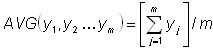
AVG |
Average of arguments |
|
SSQ |
Sum of square of arguments |
|
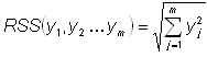
RSS |
Square root of sum of squares of arguments |
|
MAX |
Maximum of arguments |
|
MIN |
Minimum of arguments |
|
SUMABS |
Sum of absolute value of arguments |
|
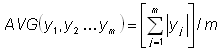
AVGABS |
Average of absolute value of arguments |
|
MAXABS |
Maximum of absolute arguments |
|
MINABS |
Minimum of absolute value of arguments |
|
RMS |
Root Mean Square value of arguments. |
|
| 25. | For RTYPE = INERTIA, the Moment of Inertia is with reference to the center of gravity. The Moment of Inertia of the whole model is referred to the center of gravity of the whole model. The Moment of Inertia of each property or material is referred to the center of gravity of that property or material. |
| 26. | For acoustic optimization, pressure responses are defined using RTYPE=FRPRES; however, it is acceptable to define a pressure response on a fluid grid as RTYPE=FRDISP with ATTA as one of M-TX, R-TX or I-TX, internally it will be converted to FRPRES (with M-TX/R-TX/I-TX interpreted as M-PRES/R-PRES/I-PRES). Likewise, RTYPE=PSDDISP or RMSDISP are accepted in place of PSDPRES or RMSPRES, respectively. |
| 27. | For RTYPE = MBDIS, MBVEL, MBACC, or MBFRC, the PTYPE must be MBREQM. These four response types must be defined using MARKERs, and requested by MBREQM. For RTYPE = MBEXPR, the PTYPE must be MBREQE. The response must be requested by MBREQE. For RTYPE = MBMASS, MBCOG, or MBINER, the PTYPE must be PFBODY. |
| 28. | MBREQE referenced in DRESP1 must have single expression although MBREQE allows up to 6 expressions for analysis output. |
| 29. | MBD system level responses must be scalar quantities. Thus, THE ATTB field must have one of the following - MAX, MIN, MAXABS, or MINABS so that time dependent vectors can be converted to scalar quantities. |
| 30. | Legacy data with RANDPS ID defined on the PTYPE or ATTB entry is also supported. |
| 31. | A blank field for RANDID on the EXTN extended attributes entry indicates that all RANDPS cards in the input file will be used. |
| 32. | For Static Stress responses for homogeneous materials, the ATTB field on the DRESP1 entry can be used to define the “Cluster Size” which may help avoid stress concentrations or gradients. “Cluster Size” affects each of the elements defined via PID or EID on the ATTi field for a particular stress response. “Cluster Size” represents the number of elements around the specified element whose stress contributions are included in the calculation of the individual element’s stress contribution. The contributions of the elements in the cluster are weighted based on their distance to the center of the cluster (Available for Shell and Solid elements). Weighting element stress contributions using “Cluster Size” is generally useful in models with stress gradients or stress concentrations in the design space. If the stress distribution within the selected element cluster is uniform, there may not be any significant difference in the stress response. A separate result type “Element Stress Cluster” is available in the _s#.h3d file and stress results based on element cluster response(s) can be viewed in HyperView by selecting Element Stresses Cluster in the Result type: drop-down menu. |
The SECTION entry can be used to define a face of the cross-section on which the forces/moments are calculated as a response in optimization runs via RTYPE=RESFORCE (on the DRESP1 entry). In such cases, Grid Point Forces or Moments are added at each GRID specified within the grid set (GSID). The effect of all elements on the grid points (GSID) is considered in the calculation of the response except the elements specified via ESID. The section is determined through a set of Grid points and the particular face is specified by a set of elements. The face is interpreted as the side of the Grid point set NOT containing the specified elements (refer to SECTION). This is similarly applicable to Rigid Element sets through RSID.
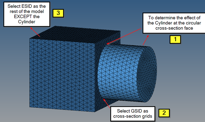
Figure 1: Defining the SECTION for the RESFORCE response
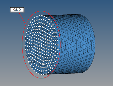
Figure 2: Selecting the GSID set
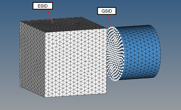
Figure 3: Selecting the corresponding ESID
The default GID is the geometric center of the cross-section. For example, in a shell model, if the cross-section is tapered (Figure 4), the geometric center is automatically updated (if the GID field is blank).
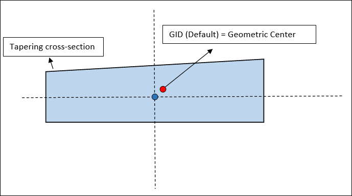
Figure 4: Geometric center via GID=Default
| 34. | Extended options are available for Frequency-based response definitions via the LOWFQ, HIGHFQ, SCALE, and OCTAVE fields on the EXTN continuation line. |
LOWFQ and HIGHFQ: Defines the Frequency Range within which the responses are determined. Additionally, the ATTB field can be used to specify functions to calculate combined responses over the frequency range.
SCALE: This field can be used to Scale and/or Weight the responses in the frequency range. (In the case of sound pressure, weighting is applied to measured (or calculated) sound levels to account for the relative loudness perceived by the human ear, which is less sensitive to low and high frequencies).
LIN (default) - The Linear Response function is output without any applied weighting or scaling.
![]()
Where, RESPLIN is the linear response function calculated for the SCALE=LIN option, Pcal is the calculated Frequency Response output.
| LOG | The logarithmic response function is output directly without any applied weighting. |
Where, RESPLOG is the Logarithmic response function calculated for the SCALE=LOG option, Pcal is the calculated Frequency Response output, and Pref is the Reference Response defined by PARAM, SPLREFDB (Default = 1.0) or the UNITS I/O Options entry.
| DBA | A-Weighting is applied to the responses within the frequency range. |
Where, RESPA( f ) is the A-Weighted frequency response output at a frequency ( f ), WA( f ) is A-Weighting factor at frequency ( f ), Pcal is the calculated Frequency Response output, and Pref is the Reference Response defined by PARAM, SPLREFDB (Default = 1.0) or the UNITS I/O Options entry.
| DBB | B-Weighting is applied to the responses within the frequency range. |
Where, RESPB( f ) is the B-Weighted Frequency Response output at a frequency ( f ), WB( f ) is B-Weighting factor at frequency ( f ), Pcal is the calculated Frequency Response output, and Pref is the Reference Response defined by PARAM, SPLREFDB (Default = 1.0) or the UNITS I/O Options entry.
| DBC | C-Weighting is applied to the responses within the frequency range. |
Where, RESPC( f ) is the C-Weighted Frequency response output at a frequency ( f ), WC( f ) is C-Weighting factor at frequency ( f ), Pcal is the calculated Frequency Response output, and Pref is the Reference Response defined by PARAM, SPLREFDB (Default = 1.0) or the UNITS I/O Options entry.
The reference response is dependent on the units specified on the UNITS I/O Options entry. If the units are SI, the value is set as 2.0E-5 Pa. If they are CGS, it is set as 2.0E-4 barye. If they are MPa, it is set as 2.0E-11 MPa. If they are BG or EE, then it is set as 4.17E-7 lbf/ft2. If no UNITS data is present, the default value is 1.0.
OCTAVE: This field can be used to specify the Octave Band types for Response calculation. Sound spectrum is usually represented in Octave or 1/3 Octave Frequency bands instead of narrow Frequency Bands. This representation is linked to the perception of sound by the human ear and it allows for compression of information across similar responses within frequency bands. Responses are accumulated for all the frequencies within the Octave band using the function specified on the OCTOPT field (see below). Full Octave, 1/3 Octave, and 1/8 Octave bands are commonly used in NVH analysis and are available (other bands are also available, if required). Weighting is also taken into account (depending on the SCALE field) prior to Response accumulation over Octave bands.
Full Octave – OCTAVE = 1
1/3 Octave – OCTAVE = 3
1/8 Octave – OCTAVE = 8
Other Octave bands are also available and can be requested similarly.
The OCTOPT field can be set to INT, SUM, or AVG. INT, the default, calculates the value under the weighted response-frequency curve for each octave band. SUM is simply the sum of the response values in each octave band. AVG is the average response in each octave band.
The ATTB field is ignored, if the OCTAVE field is specified
| 35. | Stress Responses for Topology and Free-Size optimization can be defined via the DRESP1 Bulk Data Entry. The Stress Responses are internally aggregated using the Stress-NORM approach to maintain the number of created responses at a reasonable number. |
Stress NORM Method
The Stress NORM method is used to approximately calculate the maximum value of the stresses of all the elements included in a particular response. This is also scaled with the stress bounds specified for each element. Therefore, to minimize the maximum stresses in a particular element set, the resulting stress NORM value (![]() ) is internally constrained to a value lower than 1.0.
) is internally constrained to a value lower than 1.0.
Where, ![]() is the Stress NORM value, n is the number of elements,
is the Stress NORM value, n is the number of elements, ![]() is the individual stress value of element "i",
is the individual stress value of element "i", ![]() is the stress bound for each element, and p is a penalty (power) value (default=6.0).
is the stress bound for each element, and p is a penalty (power) value (default=6.0).
The Penalty or Power value (p) can be modified using the parameter DOPTPRM, PNORM. The value p = 6.0 is the default and higher values of (p à ∞) increases the accuracy of the stress norm function (![]()
![]()
 ), which can lead to instability of the optimization run. Values lower than 6 (p
 ![]() 1) moves the stress norm function closer to the average ratio (
1) moves the stress norm function closer to the average ratio (![]()
![]()
 ). The default value is a reasonable approximation of the maximum ratio value and reduces instability.
RTYPE=VOLUME and ATTA=ENCLOSED can be used to create an enclosed volume response for Shape, Free-Shape, and Topography optimization. The ENCLOSED option indicates that this response is an enclosed volume defined by a closed 2D mesh (free-edges are not supported). For this enclosed volume response type, ATTI field(s) should be set to PID.
| 36. | The ATTB field can be set to RMS or ZCF for RMS responses. ATTB=RMS represents the RMS response, ATTB=ZCF represents the Zero Crossing Frequency response based on the corresponding RMS response (see Random Response Analysis in the User's Guide for further information regarding Zero Crossing). |
| 37. | Surface stress responses can be defined for solid elements by using RTYPE=STRESS and using one or more of the Surface stress response Item Codes (SVMS, SMPS, and SMIPS). |
| 38. | This card is represented as an optimization response in HyperMesh. |
See Also: