|
»Click here to display Table of Contents«
|

Responses |

|

|

|

|
|
Responses |
|
|

|

|
|
»Click here to display Table of Contents«
|
Responses |
|
|
|
|
|
Responses |
|
|
|
|
The following responses can be found in this section:
OptiStruct allows the use of numerous structural responses, calculated in a finite element analysis, or combinations of these responses to be used as objective and constraint functions in a structural optimization. Responses are defined using DRESP1 bulk data entries. Combinations of responses are defined using either DRESP2 entries, which reference an equation defined by a DEQATN bulk data entry, or DRESP3 entries, which make use of user-defined external routines identified by the LOADLIB I/O option. Responses are either global or subcase (loadstep, load case) related. The character of a response determines whether or not a constraint or objective referencing that particular response needs to be referenced within a subcase. Subcase IndependentMass and VolumeBoth are global responses that can be defined for the whole structure, for individual properties (components) and materials, or for groups of properties (components) and materials. It is not recommended to use mass and volume as constraints or objectives in a topography optimization. Neither is very sensitive towards design modifications made in a topography optimization. In order to constrain the mass or volume for a region containing a number of properties (components), the SUM function can be used to sum the mass or volume of the selected properties (components), otherwise, the constraint is assumed to apply to each individual property (component) within the region. Alternatively, a DRESP2 equation needs to be defined to sum the mass or volume of these properties (components). This can be avoided by having all properties (components) use the same material and applying the mass or volume constraint to that material. RTYPE=VOLUME and ATTA=ENCLOSED can be used to create an enclosed volume response for Shape, Free-Shape, and Topography optimization. The ENCLOSED option indicates that this response is an enclosed volume defined by a closed 2D mesh (free-edges are not supported). For this enclosed volume response type, ATTI field(s) should be set to PID. Multiple ATTi are allowed, as long as the mesh defined by the PID’s is fully enclosed. The property type should be PSHELL, PCOMP, or PSHEAR only. The normals of the 2D mesh should be oriented consistently and the mesh should be sufficiently fine to capture the volume data. The volume is calculated based on the mesh and it is not recommended to use a coarse mesh. Fraction of Mass and Fraction of Design VolumeBoth are global responses with values between 0.0 and 1.0. They describe a fraction of the initial design space in a topology optimization. They can be defined for the whole structure, for individual properties (components) and materials, or for groups of properties (components) and materials. The difference between the mass fraction and the volume fraction is that the mass fraction includes the non-design mass in the fraction calculation, whereas the volume fraction only considers the design volume. Formulation for volume fraction: Formulation for mass fraction: If, in addition to the topology optimization, a size and shape optimization is performed, the reference value for the volume fraction (the initial design volume) is not altered by size and shape changes. This can, on occasion, lead to negative values for this response. Therefore, if size and shape optimization is involved, it is recommended to use the Volume responses instead of the Volume Fraction response. These responses can only be applied to topology design domains. OptiStruct will terminate with an error if this is not the case. Center of GravityThis is a global response that may be defined for the whole structure, for individual properties (components) and materials, or for groups of properties (components) and materials. Moments of InertiaThis is a global response that may be defined for the whole structure, for individual properties (components) and materials, or for groups of properties (components) and materials. Weighted ComplianceThe weighted compliance is a method used to consider multiple subcases (loadsteps, load cases) in a classical topology optimization. The response is the weighted sum of the compliance of each individual subcase (loadstep, load case).
This is a global response that is defined for the whole structure. Weighted Reciprocal Eigenvalue (Frequency)The weighted reciprocal eigenvalue is a method to consider multiple frequencies in a classical topology optimization. The response is the weighted sum of the reciprocal eigenvalues of each individual mode considered in the optimization.
This is done so that increasing the frequencies of the lower modes will have a larger effect on the objective function than increasing the frequencies of the higher modes. If the frequencies of all modes were simply added together, OptiStruct would put more effort into increasing the higher modes than the lower modes. This is a global response that is defined for the whole structure. Combined Compliance IndexThe combined compliance index is a method to consider multiple frequencies and static subcases (loadsteps, load cases) combined in a classical topology optimization. The index is defined as follows:
This is a global response that is defined for the whole structure. The normalization factor, NORM, is used to normalize the contributions of compliances and eigenvalues. A typical structural compliance value is of the order of 1.0e4 to 1.0e6. However, a typical inverse eigenvalue is on the order of 1.0e-5. If NORM is not used, the linear static compliance requirements dominate the solution. The quantity NORM is typically computed using the formula:
Where, Cmax is the highest compliance value in all subcases (loadsteps, load cases) and In a new design problem, you may not have a close estimate for NORM. If this happens, OptiStruct automatically computes the NORM value based on compliances and eigenvalues computed in the first iteration step. Stress Responses for Topology and Free-Size Optimization Actual Stress Responses for Topology and Free-Size Optimization are available through corresponding Stress response RTYPE’s on the DRESP1 Bulk Data Entry. The Stress-NORM aggregation is internally used to calculate the Stress Responses for groups of elements in the model. von Mises Stress in a Topology or Free-Size OptimizationAdditionally, von Mises stress constraints may be defined for topology and free-size optimization through the STRESS optional continuation line on the DTPL or the DSIZE card. There are a number of restrictions with this constraint:
Bead Discreteness FractionThis is a global response for topography design domains. This response indicates the amount of shape variation for one or more topography design domains. The response varies in the range 0.0 to 1.0 (0.0 < BEADFRAC < 1.0), where 0.0 indicates that no shape variation has occurred, and 1.0 indicates that the entire topography design domain has assumed the maximum allowed shape variation. Random Response AnalysisPSD and RMS ResponsesPSD displacement, PSD velocity, PSD acceleration, PSD acoustic pressure, PSD stress, PSD strain, RMS displacement, RMS velocity, RMS acceleration, RMS acoustic pressure, RMS stress, and RMS strain responses are available as global, as well as subcase-dependent responses (this information is also available in the Subcase Dependent responses section below). Subcase DependentLinear Static AnalysisStatic ComplianceThe compliance C is calculated using the following relationship:
or
For a structure with an applied forces f subcase, the compliance C can be considered a reciprocal measure of the stiffness K:
Where, For maximum stiffness K, the compliance C can be minimized. For a structure with an applied displacements u subcase, the compliance C can be considered a direct measure of the stiffness K:
Where, Elements in the ComplianceCompliance can be defined for the whole structure, for individual properties (components) and materials, or for groups of properties (components) and materials. The compliance must be assigned to a linear static subcase (loadstep, load case). In order to constrain the compliance for a region containing a number of properties (components), the SUM function can be used to sum the compliance of the selected properties (components), otherwise, the constraint is assumed to apply to each individual property (component) within the region. Alternatively, a DRESP2 equation needs to be defined to sum the compliance of these properties (components). This can be avoided by having all properties (components) use the same material and applying the compliance constraint to that material. Static DisplacementDisplacements are the result of a linear static analysis. Nodal displacements can be selected as a response. They can be selected as vector components or as absolute measures. They must be assigned to a linear static subcase. Static Stress of Homogeneous MaterialDifferent stress types can be defined as responses. They are defined for components, properties, or elements. Element stresses are used, and constraint screening is applied. It is also not possible to define static stress constraints in a topology design space (see above). This is a linear static subcase (loadstep, load case) related response. Static Strain of Homogeneous MaterialDifferent strain types can be defined as responses. They are defined for components, properties, or elements. Element strains are used, and constraint screening is applied. It is also not possible to define strain constraints in a topology design space. This is a linear static subcase (loadstep, load case) related response. Static Stress of Composite Lay-upDifferent composite stress types can be defined as responses. They are defined for PCOMP(G) components or elements, or PLY type properties. Ply level results are used, and constraint screening is applied. It is also not possible to define composite stress constraints in a topology design space. This is a linear static subcase (loadstep, load case) related response. Static Strain of Composite Lay-upDifferent composite strain types can be defined as responses. They are defined for PCOMP(G) components or elements, or PLY type properties. Ply level results are used, and constraint screening is applied. It is also not possible to define composite strain constraints in a topology design space. This is a linear static subcase (loadstep, load case) related response. Static Failure in a Composite Lay-upDifferent composite failure criterion can be defined as responses. They are defined for PCOMP(G) components or elements, or PLY type properties. Ply level results are used, and constraint screening is applied. It is also not possible to define composite failure criterion constraints in a topology design space. This is a linear static subcase (loadstep, load case) related response. Static ForceDifferent force types can be defined as responses. They are defined for components, properties, or elements. Constraint screening is applied. It is also not possible to define force constraints in a topology design space. This is a linear static subcase (loadstep, load case) related response. Single Point Force at a constrained grid pointThis response can be defined using the DRESP1 bulk data entry (RTYPE=SPCFORCE). This response is defined for constrained grid points. Constraint screening is applied to this response. This is a linear static subcase (loadstep, load case) related response. Grid Point ForceThis response can be defined using the DRESP1 bulk data entry (RTYPE=GPFORCE). This response defines the contribution to a specific grid point force component from a non-rigid element (which is connected to that grid). Constraint screening is applied to this response. If ATTi specify multiple elements, then multiple responses will be generated; where, each response calculates a specified element’s contribution to the grid point force component at the specified grid. This is a linear static subcase (loadstep, load case) related response. Heat Transfer AnalysisTemperatureTemperatures are the result of a heat transfer analysis, and must be assigned to a heat transfer subcase (loadstep, load case). Temperature response cannot be used in composite topology and free-size optimization. Thermal ComplianceThermal compliance C is calculated using:
Where, T is the temperature vector, f is the power vector, KC is the conduction matrix, and H is the convection matrix. Thermal compliance is a global measure for structural heat transfer problem. It is calculated for the entire structure. Thermal compliance must be assigned to a linear steady state heat transfer subcase (loadstep, load case). When minimizing thermal compliance, temperatures at grids of flux input are minimized. The optimum structure provides maximum conduction of thermal energy. Since thermal compliance is a smooth convex function, it is typically more efficient to minimize thermal compliance than to perform a min-max of the temperature of the entire structure. During thermal-structural optimization, the temperature field is updated for each iteration. Additionally, for thermal-structural topology optimization, the density design variable affects the conductivity, and the conductivity is also penalized. Thermal Compliance Response can only be used in Sizing, Shape, Topology, and Free-Size Optimization. Normal Modes AnalysisFrequencyNatural frequencies are the result of a normal modes analysis, and must be assigned to the normal modes subcase (loadstep, load case). It is recommended to constrain the frequency for several of the lower modes, not just of the first mode. There are two ways to use Normal Mode response in an Optimization run:
Mode ShapeMode shapes are the result of a normal modes analysis. Mode shapes can be selected as a response. They can be selected as vector components or as absolute measures. They must be assigned to a normal modes subcase. Linear Buckling AnalysisBuckling FactorThe buckling factor is the result of a buckling analysis, and must be assigned to a buckling subcase (loadstep, load case). A typical buckling constraint is a lower bound of 1.0, indicating that the structure is not to buckle with the given static load. It is recommended to constrain the buckling factor for several of the lower modes, not just of the first mode. Frequency Response Function (FRF Analysis)Frequency Response DisplacementDisplacements are the result of a frequency response analysis. Nodal displacements, i.e. translational, rotational and normal*, can be selected as a response. They can be selected as vector components in real/imaginary or magnitude/phase form. They must be assigned to a frequency response subcase (loadstep, load case). *The normal at a grid point is calculated based on the normals of the surrounding elements. The normal frequency response displacement at a grid point can be selected as a response and it is the displacement in the normal’s direction. The normals are also updated when shape changes occur during shape optimization. Frequency Response VelocityVelocities are the result of a frequency response analysis. Nodal velocities, i.e. translational, rotational and normal*, can be selected as a response. They can be selected as vector components in real/imaginary or magnitude/phase form. They must be assigned to a frequency response subcase (loadstep, load case). *The normal at a grid point is calculated based on the normals of the surrounding elements. The normal frequency response velocity at a grid point can be selected as a response and it is the velocity in the normal’s direction. The normals are also updated when shape changes occur during shape optimization. Frequency Response AccelerationAccelerations are the result of a frequency response analysis. Nodal accelerations, i.e. translational, rotational and normal*, can be selected as a response. They can be selected as vector components in real/imaginary or magnitude/phase form. They must be assigned to a frequency response subcase (loadstep, load case). *The normal at a grid point is calculated based on the normals of the surrounding elements. The normal frequency response acceleration at a grid point can be selected as a response and it is the acceleration in the normal’s direction. The normals are also updated when shape changes occur during shape optimization. Frequency Response StressDifferent stress types can be defined as responses. They are defined for components, properties, or elements. Element stresses are not used in real/imaginary or magnitude/phase form, and constraint screening is applied. The von Mises stress for solids and shells can also be defined as direct responses. It is not possible to define stress constraints in a topology design space. This is a frequency response subcase (loadstep, load case) related response. Frequency Response StrainDifferent strain types can be defined as responses. They are defined for components, properties, or elements. Element strains are used in real/imaginary or magnitude/phase form, and constraint screening is applied. The von Mises strain for solids and shells can also be defined as direct responses. It is not possible to define strain constraints in a topology design space. This is a frequency response subcase (loadstep, load case) related response. Frequency Response ForceDifferent force types can be defined as responses. They are defined for components, properties, or elements in real/imaginary or magnitude/phase form. Constraint screening is applied. It is also not possible to define force constraints in a topology design space. This is a frequency response subcase (loadstep, load case) related response. Random Response AnalysisPSD and RMS ResponsesPSD displacement, PSD velocity, PSD acceleration, PSD acoustic pressure, PSD stress, PSD strain, RMS displacement, RMS velocity, RMS acceleration, RMS acoustic pressure, RMS stress and RMS strain responses are available as global as well as subcase-dependent responses (this information is also available in the Subcase Independent responses section above). Coupled FRF Analysis on a Fluid-structure Model (Acoustic Analysis)Acoustic PressureAcoustic pressures are the result of a coupled frequency response analysis on a fluid-structure model. This response is available for fluid grids. It must be assigned to a coupled frequency response subcase (loadstep, load case) on a fluid-structure model. Multi-body Dynamics AnalysisFlexible Body ResponsesFor Multi-body Dynamics problems, the Mass, Center of gravity, and Moment of Inertia of one or more flexible bodies are available as responses. This is in addition to other usual structural responses. MBD DisplacementMBD displacements are the result of a multi-body dynamics analysis. They must be assigned to a multi-body dynamics subcase (loadstep, load case). MBD VelocityMBD velocities are the result of a multi-body dynamics analysis. They must be assigned to a multi-body dynamics subcase (loadstep, load case). MBD AccelerationMBD acceleration are the result of a multi-body dynamics analysis. They must be assigned to a multi-body dynamics subcase (loadstep, load case). MBD ForceMBD forces are the result of a multi-body dynamics analysis. They must be assigned to a multi-body dynamics subcase (loadstep, load case). MBD ExpressionMBD expression responses are the result of a multi-body dynamics analysis. They are the result of the evaluation of an expression. They must be assigned to a multi-body dynamics subcase (loadstep, load case). FatigueLife/DamageLife and Damage are results of a fatigue analysis. They must be assigned to a Fatigue subcase. Dynamic/Nonlinear AnalysisEquivalent Plastic StrainEquivalent plastic strain can be used as an internal response when a nonlinear response optimization is run using the equivalent static load method. This is made possible through the use of an approximated correlation between linear strain and plastic strain, which are calculated in the inner and outer loops respectively, of the ESL method. ESL VelocityESL velocity can be used as an internal response, when a nonlinear response optimization is run, using the equivalent static load method. The RTYPE=ESLV option can be used in conjunction with the velocity component value and a GRID ID specification. User ResponsesFunctionA function response is one that uses a mathematical expression to combine design variables, grid point locations, responses, and/or table entries. Whether the function is subcase (loadstep, load case) related or global, is dependent on the response types used in the equation. ExternalAn external response is one that uses an external user-defined routine to combine design variables, grid point locations, eigenvectors, responses, and/or table entries. Whether the function is subcase (loadstep, load case) related or global is dependent on the response types used in the routine. Refer to External Responses below for more information. |
The DRESP3 bulk data entry, in combination with the LOADLIB I/O option entry, allows for the definition of responses through user-defined external functions. The external functions may be written in HyperMath Language (HML), FORTRAN, C or a Microsoft Excel workbook. The resulting libraries and files should be accessible by OptiStruct regardless of the coding language, providing that consistent function prototyping is respected, and adequate compiling and linking options are used. Writing External FunctionsThe OptiStruct installation provides "barebone" functions for FORTRAN (dresp3_barebone.F) and for C (dresp3_barebone.c) with proper function definition, arguments, and compilation directives. These files can be used as starting points to write your own functions. Refer to Referencing External Files for information on response definition through a user-defined Microsoft Excel workbook. HyperMath Language (HML) functions are defined as follows: integer function myfunct(iparam, rparam, iresp, rresp, userdata) If sensitivities need to be requested, then the following external function can be used. integer function myfunct(iparam, rparam, iresp, rresp, dresp, isens userdata)
FORTRAN functions are defined as follows: integer function myfunct(iparam, rparam, nparam, iresp, rresp, nresp, userdata)
If sensitivities need to be requested, then the following external function can be used. integer function myfunct(iparam, rparam, nparam, iresp, rresp, dresp, nresp, isens userdata)
character*32000 userdata integer nparam, nresp integer iparam(nparam), iresp(nresp) double precision param(nparam), rresp(nresp), dresp(nparam,nresp)
C functions are defined as follows: int myfunct(int* iparam, double* rparam, int* nparam, int* iresp, double* rresp, int* nresp, char* userdata)
If sensitivities need to be requested, then the following external function can be used. int myfunct(int* iparam, double* rparam, int* nparam, int* iresp, double* rresp, double* dresp, int* nresp, int* isens, char* userdata) Note that the functions' arguments are identical in both languages so as to preserve compatibility. However, since FORTRAN always passes arguments by address, it is important to understand that external C functions receive pointers instead of variables. In order to ensure portability, the following must be adhered to:
Regarding implementing of external, user-defined routines using HyperMath, refer to the online documentation for writing scripts in HyperMath. HyperMath is supported on the Windows and Linux operating systems only. Function Return ValuesExternal functions should return 0 or 1 for successful completion, where 1 indicates that a user-defined information message should be output by OptiStruct. External functions should return -1 in case of fatal error, in which case OptiStruct will terminate after outputting a user-defined error message. See below for more information about error and information messages. Function ArgumentsThe following table briefly describes the arguments which are passed from OptiStruct to the external functions.
Parameters:
Parameter values are passed in the exact order in which they were defined on the DRESP3 card, regardless of their type. Using the parameter types table is optional, for instance to perform verifications or code-branching. The following types are currently supported:
Responses:
The responses requests table indicates which of the available responses are actually needed by OptiStruct. Entries in iresp(nresp) are flagged as 1 for requested responses and as 0 otherwise. Using that information is optional, and allows for saving computational effort by not evaluating responses which OptiStruct does not need. Userdata StringUpon entering the function, the userdata string contains data as defined in the USRDATA field of the DRESP3 card. It provides a convenient mechanism to pass constants or any other relevant information to the function. There are no restrictions regarding the contents of the string, but its length must not exceed 32,000 characters. Upon exiting the function, the string may contain a user-defined error or information message. The updated string is then returned to OptiStruct, where it is printed to the standard output (.out file and/or screen). Here again, the contents of the string are not restricted as long as its length does not exceed 32,000 characters. The error or information messages may be formatted by using the character "|" as a line-break indicator. Standard C escape sequences are supported, as well. It is advised, but not necessary, to format messages in such a way that each line does not exceed 80 characters, since the same convention is used in OptiStruct's output files. Sensitivity Flag
Building External LibrariesWindows Systems with Microsoft Developer StudioCreating dynamic libraries under Windows with Microsoft Developer Studio is an extremely easy task. Simply start a new project and select either "FORTRAN Dynamic Link Library" for FORTRAN, or "Win32 Dynamic-Link Library" for C. For FORTRAN libraries, you need to change the argument passing conventions in the project settings. Under the "FORTRAN" tab, select the category "External Procedures" and then change the "Argument Passing Conventions" to "C, By Reference". On Windows systems, %PATH% must be set correctly to ensure that the right compiler DLLs are picked up at runtime. UNIX SystemsUnder UNIX, the general syntax to build a shared library starting from a FORTRAN or C file is:
Where, FC refers to the FORTRAN compiler (for instance f77), CC refers to the C compiler (for instance cc or gcc), and LD refers to the linker (for instance ld) installed on your computer. Refer to your system's manuals for more information. The compiler and linker options provide information about the platform you are building the library for. The linker options also specify that you are building a shared library. Other options, such as code optimization parameters, are left to your discretion and should not usually affect the compatibility with OptiStruct. The following table defines options for each of OptiStruct's release platforms, which have been verified to work correctly on various systems. Keep in mind that these options might change depending on the compilers and linker installed on your computer, so refer to your operating system manual for further information. In most cases GNU compilers can be used in place of Intel compilers. Use the appropriate compiler and linker options to create a shared library with the compiler of your choice. The compilers and versions in the following table are the ones used to build OptiStruct.
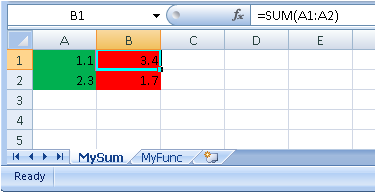
If Compaq Visual Fortran is used to build the external response functions called by DRESP3, the following compiler directive is required to export the functions appropriately: For a function – “myfunc” integer function myfunc (iparam, rparam, nparam, iresp, rresp, dresp, nresp, isens, userdata) cDEC$ ATTRIBUTES DLLEXPORT, C, REFERENCE :: myfunc Compiler and linker options for Compaq Visual Fortran, similar to those given in the above table, will be required to build and use multithreaded dynamic runtime libraries. Once your library is built, you can verify that the functions have been exported correctly by using nm mylib.so on UNIX systems and dumpbin /exports mylib.dll on Windows systems with Microsoft Developer Studio. This command will display the list of symbols found in the library, among which you should recognize the function(s) which you have written. Note that some FORTRAN compilers convert function names to lower-case or upper-case symbols, and some compilers also append an underscore to these names. However, in your input decks, you do not have to worry about the exact symbol name. Simply use the function name as it is defined in your code, and OptiStruct will automatically locate the appropriate symbol. Using External LibrariesAll files referenced here are located in the HyperWorks installation directory under <install_directory>/demos/os/manual/. To locate the HyperWorks installation directory, <install_directory>, use the following approach: From the permanent menu, select the global panel and review the path next to template file: <install_directory> is the portion of the path preceding the templates/ directory on PC, and the hm/ directory on UNIX. HyperMath ExampleRefer to the OptiStruct tutorial, OS-4095 (Size Optimization using External Responses (DRESP3) through HyperMath), for information on using DRESP3 with HyperMath to implement external, user-defined routines. Simple ExampleThe files dresp3_simple.F and dresp3_simple.c contain source code for simple examples of external functions written in FORTRAN and C, respectively. Both functions are named mysum and compute two responses – the sum of the parameters and the averaged sum of the parameters. The input deck dresp3_simple.fem contains an example problem calling both of these external functions. Two LOADLIB cards referring to the FORTRAN and C libraries are defined: LOADLIB DRESP3 FLIB dresp3_simple_f.dll You have created four DRESP3 cards, which are pointing to the FORTRAN and C functions and requesting the first and second responses in each of those functions. Two DRESP1 responses are used as parameters: DRESP3 6 SUMF FLIB MYSUM 1 2 For verification purposes, you have also defined two DRESP2 cards that are pointing to two simple equations which evaluate the sum and the averaged sum of their parameters: DEQATN 1 F(x,y) = x+y Running this input deck through OptiStruct shows that the FORTRAN external functions, the C external functions and the internal equations always return the same values, and are updated simultaneously throughout the optimization process. Advanced ExampleThe file dresp3_advanced.F contains the FORTRAN source code of the second example, in which you are making use of advanced features of the DRESP3 functionality. The external function is able to compute the von Mises and maximum principal stresses (strains) of an element based on its stress (strains) components. Either 3 or 6 components can be passed as parameters – 3 components for a shell element and 6 components for a solid element. The following features are used:
The input deck dresp3_advanced.fem gives a simple example of problem making use of this external function, for analysis only. The DRESP1 responses 10-12 and 13-18 correspond to the stress components of a 2D and a 3D element, respectively. The DRESP1 responses 20-23 evaluate the von Mises stress and the maximum principal stress of the same two elements: DRESP1 10 SXX2D STRESS ELEM SX1 100 In addition, you have defined DRESP3 cards which compute the same stress results through our external library. You are also using the SLAVE feature to clone the parameters of similar cards: DRESP3 30 SVM2D-3 STRLIB GETSTR 1 2 Referencing External FilesMicrosoft Excel workbooks can be referenced via the LOADLIB entry to define user-defined responses. Both Implicit and Explicit options are available and are defined as follows: Implicit definitionThis is a simple implementation wherein two columns in an Excel worksheet are used to define the input and output parameters. Column 1 can be used to list input parameters and Column 2 can be used to list output parameters.
LOADLIB DRESP3 ELIB dresp3_excel.xlsx
DRESP3 10 SUM ELIB MYSUM + DRESP1 5 6
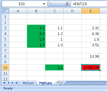
Explicit definitionIn this advanced implementation, the cell input number is specified. Cells for input and output data are listed. LOADLIB DRESP3 ELIB dresp3_excel.xlsx DRESP3 20 FUNC ELIB MYFUNC + DRESP1 5 6 7 8 + DESVAR 1 + CELLIN B3 through B6 + CELLIN C10 + CELLOUT E10
|