|
»Click here to display Table of Contents«
|

DSHUFFLE |

|

|

|

|
|
DSHUFFLE |
|
|
|

|
|
»Click here to display Table of Contents«
|
DSHUFFLE |
|
|
|
|
|
DSHUFFLE |
|
|
|
|
DSHUFFLE – Design Variable for Composite Shuffling Optimization
Defines parameters for the generation of composite shuffling design variables.
(1) |
(2) |
(3) |
(4) |
(5) |
(6) |
(7) |
(8) |
(9) |
(10) |
DSHUFFLE |
ID |
ETYPE |
EID1 |
EID2 |
EID3 |
EID4 |
EID5 |
EID6 |
|
+ |
|
EID7 |
… |
|
|
|
|
|
|
+ |
MAXSUCC |
MANGLE |
MSUCC |
VSUCC |
|
|
|
|
|
+ |
|
|
|
|
|
|
|
|
|
+ |
PAIR |
PANGLE1 |
PANGLE2 |
POPT |
|
|
|
|
|
+ |
CORE |
CREP |
CANG1 |
CANG2 |
CANG3 |
CANG4 |
CANG5 |
CANG6 |
|
+ |
|
|
CANG7 |
… |
|
|
|
|
|
+ |
COVER |
VREP |
VANG1 |
VANG2 |
VANG3 |
VANG4 |
VANG5 |
VANG6 |
|
+ |
|
|
VANG7 |
… |
|
|
|
|
|
+ |
RANGE |
PIDSTA |
PIDEND |
|
|
|
|
|
|
Field |
Contents |
ID |
Unique identification number. No default (Integer > 0) |
ETYPE |
Entity type for which this DSHUFFLE card is defined. No default (STACK, PCOMP, or PCOMPG) |
EID# |
Entity identification numbers. List of entities of type ETYPE for which this DSHUFFLE card is defined. No default (Integer > 0) |
MAXSUCC |
Indicates that the "maximum number of successive plies" constraint is applied. Multiple MAXSUCC constraints are allowed (Comment 1). |
MANGLE |
Ply orientation, in degrees, to which the MAXSUCC constraint is applied. No default (Real or ALL) |
MSUCC |
Maximum number of successive plies for the MAXSUCC constraint. No default (Integer > 0) |
VSUCC |
Allowable percentage violation for the MAXSUCC constraint. 0.0 indicates that this constraint cannot be violated. Default = 0.0 (Real) |
PAIR |
Indicates that a pairing constraint is applied (Comment 2). |
PANGLE1 |
First ply orientation, in degrees, to which the PAIR constraint is applied. No default (Real, only 45.0 allowed at this time) |
PANGLE2 |
Second ply orientation, in degrees, to which the PAIR constraint is applied. No default (Real, only -45.0 allowed at this time) |
POPT |
Pairing option. SAME indicates that the stacking sequence should remain the same for consecutive pairs. REVERSE indicates that the stacking sequence should be reversed for alternate pairs. Default = blank (SAME, REVERSE or BLANK) |
CORE |
Indicates that a ply sequence for the core layer is defined. Only one CORE sequence is allowed (Comment 3). |
CREP |
Number of times the core ply sequence should be repeated. Default = 1 (Integer > 0) |
CANG# |
Ply orientations, in degrees, defining the core. No default (Real) |
COVER |
Indicates that a ply sequence for the cover layer is defined. Only one COVER sequence is allowed (Comment 3). |
VREP |
Number of times the cover ply sequence should be repeated. Default = 1 (Integer > 0) |
VANG# |
Ply orientations, in degrees, defining the cover. No default (Real) |
RANGE |
Indicates that starting and ending ply identification numbers are defined in the following fields to specify the range of plies to be shuffled. OptiStruct will only shuffle plies between PIDSTA and PIDEND. Multiple DSHUFFLE entries can be created to define different ply ranges. |
PIDSTA |
The ply identification number (starting ply) that defines the first ply in the range to be shuffled. No default (Integer > 0) |
PIDEND |
The ply identification number (ending ply) that defines the last ply in the range to be shuffled. No default (Integer > 0) |
Comments
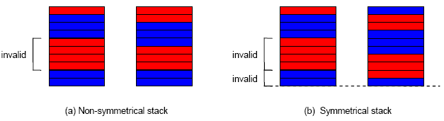
| 1. | The MAXSUCC constraint indicates that the stacking sequence should contain no sections with more than a given number of successive plies with the same orientation. In the case of symmetrical laminates, this constraint accounts for the mirrored successive plies on both sides of the symmetry plane. In the image below, (a) shows invalid and valid sequences for a non-symmetrical stack, and (b) shows invalid and valid sequences for a symmetrical stack, both for MAXSUCC=3. |
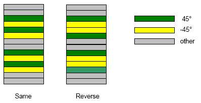
| 2. | The PAIR constraint indicates that 45° and -45° plies should be paired together. The POPT option specifies how the pairing should be accomplished, as illustrated on the figure below. |
| 3. | The CORE and COVER constraints specify stacking sequences for the core and cover layers, respectively. Plies are listed from the bottom surface upward, in respect to the element’s normal direction. In the example below, the sequence for the core is (0°, 0°, 90°, and 90°) while the sequence for the cover is defined as (90°, 90°, 0°, and 0°). |
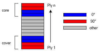
Note that, for non-symmetrical laminates, COVER actually corresponds to the bottom cover, whereas CORE corresponds to the upper cover. At this point, it is not possible to create an actual core for non-symmetrical stacks.
| 4. | For a more detailed description and an example, refer to Optimization of Composite Structures in the User’s Guide. |
| 5. | This card is represented as an optimization design variable in HyperMesh. |
See Also: