|
»Click here to display Table of Contents«
|

DSHAPE |

|

|

|

|
|
DSHAPE |
|
|
|

|
|
»Click here to display Table of Contents«
|
DSHAPE |
|
|
|
|
|
DSHAPE |
|
|
|
|
DSHAPE – Design Variable for Free-Shape Optimization
Defines parameters for the generation of free-shape design variables.
(1) |
(2) |
(3) |
(4) |
(5) |
(6) |
(7) |
(8) |
(9) |
(10) |
DSHAPE |
ID |
|
|
|
|
|
|
|
|
|
PERT |
DTYPE |
MVFACTOR |
NSMOOTH |
MXSHRK |
MXGROW |
SMETHOD |
NTRANS |
|
|
GRID |
GMETH |
GSETID1/ GID1 |
GID2/GSETID2 |
GID3/GSETID3 |
GID4/GSETID4 |
GID5/GSETID5 |
GID6/GSETID6 |
|
|
|
GID7/GSETID7 |
GID8/GSETID8 |
… |
… |
|
|
|
|
|
PATRN |
TYP |
AID/XA |
YA |
ZA |
FID/XF |
YF |
ZF |
|
|
DRAW |
DTYP |
DAID/XDA |
YDA |
ZDA |
DFID/XDF |
YDF |
ZDF |
|
|
|
DRAFT |
|
|
|
|
|
|
|
|
EXTR |
ECID |
XE |
YE |
ZE |
|
|
|
|
|
GRIDCON |
GCMETH |
GCSETID1 / GDID1 |
CTYPE1 |
CID1 |
X1 |
Y1 |
Z1 |
|
|
|
GCMETH |
GCSETID2 / GDID2 |
CTYPE2 |
CID2 |
X2 |
Y2 |
Z2 |
|
|
|
… |
… |
|
|
|
|
|
|
|
SDCON |
SDCID1 |
XL1 |
XU1 |
YL1 |
YU1 |
ZL1 |
ZU1 |
|
|
|
SDCID2 |
XL2 |
XU2 |
YL2 |
YU2 |
ZL2 |
ZU2 |
|
|
|
… |
… |
|
|
|
|
|
|
|
BMESH |
BMID |
|
|
|
|
|
|
|
|
FSSPLIT |
SPLIT |
|
|
|
|
|
|
|
Field |
Contents |
|---|---|
ID |
Each DSHAPE card must have a unique ID. No default (Integer > 0) |
PERT |
Indicates perturbation information is to follow. |
DTYPE |
Specifies the direction type for the free-shape variation. GROW – grids cannot move inside of the initial part boundary. SHRINK – grids cannot move outside of the initial part boundary. BOTH – grids are unconstrained. Default = BOTH |
MVFACTOR |
Initial limit on the movement factor of the design grids. The unit of MVFACTOR is the average mesh size of meshes adjacent to grids defined after GRID. Only the initial value of this limit can be set. The values in subsequent optimization iterations are automatically adjusted to enhance to enhance iterative stability and convergence speed; however, they will never be greater than the initial limit. Default = 0.5 (Real > 0.0) |
NSMOOTH |
Number of grids layers NSMOOTH. Default = 10 (Integer) |
MXSHRK |
Maximum shrinking distance. No default |
MXGROW |
Maximum growing distance. No default |
SMETHOD |
Mesh smoothing method. Default = 1 (1 or 2) Method 1 is faster than method 2, but method 2 is more robust in avoiding mesh distortion. |
NTRANS |
Number of design grid layers in the transition zone to non-design area, where additional treatment will be applied to produce smooth transition (Comment 2). Default = 0 (Integer > 0) |
GRID |
Indicates that a list of grid IDs or grid sets is to follow (depending on the value of the GMETH field). These grids are design variables for the free-shape optimization. |
GMETH |
Field indicating whether grids are to be defined by a list of grid IDs or as Grid SET references. If ID is specified, the following fields on this continuation line are grid point IDs. If SET is specified, the following fields on this continuation line are grid SET id’s. Default = ID (SET or ID) |
GID# |
Grid identification numbers. List of grids for which this DSHAPE card is defined (only valid if GMETH field is set to ID). No default (Integer > 0) |
GSETID# |
Grid SET identification number. A grid set containing design grids for free-shape optimization (only valid if GMETH field is set to SET). No default (Integer > 0) |
PATRN |
Indicates that variable pattern grouping is active. Indicates that information about the pattern group will follow. |
TYP |
Type of variable pattern grouping. Required if any symmetry or variable pattern grouping is desired. Only 1-plane symmetry (TYP=10) is currently supported. Default = 0 (0 or 10) |
AID/XA, YA, ZA |
Variable pattern grouping anchor point. These fields define a point that determines how grids are grouped into variables (Comment 1). The X, Y, and Z values are in the global coordinate system. You may put a grid ID in the AID/XA field to define the anchor point. Default = origin (Real in all three fields or Integer in AID/XA field) |
FID/XF, YF, ZF |
Direction of first vector for variable pattern grouping. These fields define an xyz vector which determines how grids are grouped into variables (Comment 1). The X, Y, and Z values are in the global coordinate system. If FID is defined, it defines a vector pointing from grid AID or point (XA, YA, and ZA) to grid FID. If XF, YF, ZF are defined, it defines a vector pointing from point (XA, YA, and ZA) to point (XA+XF,YA+YF,ZA+ZF). (XA, YA, and ZA) are coordinates of the anchor point defined by AID or XA, YA, and ZA. If all fields are blank and the TYP field is not blank or zero, OptiStruct gives an error. No default |
DRAW |
Indicates that casting constraints are being applied. Indicates that draw direction information is to follow. Only valid for design grids on solid elements. |
DTYP |
Type of draw direction constraint to be used. SINGLE indicates that a single die will be used, the die being withdrawn in the given draw direction. Only SINGLE is available in 9.0. |
DAID/XDA, YDA, ZDA |
Draw direction anchor point. These fields define the anchor point for draw direction of the casting. The point may be defined by entering a grid ID in the DAID field or by entering X, Y, and Z coordinates in the XDA, YDA, and ZDA fields, these coordinates will be in the basic coordinate system. Default = origin (Real in all three fields or Integer in first field) |
DFID/XDF, YDF, ZDF |
Direction of vector for draw direction definition. These fields define a point. The vector goes from the anchor point to this point. The point may be defined by entering a grid ID in the DFID field or by entering X, Y, and Z coordinates in the XDF, YDF, and ZDF fields, these coordinates will be in the basic coordinate system. No default (Real in all three fields or Integer in first field) |
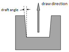
DRAFT |
Draft angle in degrees. See comment 5. Default = 0.0 (0.0 < Real < 90.0) |
SDCON# |
Indicates that side constraints are being applied. |
SDCID# |
The ID of a coordinate system which the following XL#, XU#, YL#, YU#, ZL#, or ZU# components are resolved in. |
XL#, XU#, YL#, YU#, ZL#, ZU# |
Side constraints defined by lower and upper bounds of coordinates, which restrict the moving space of the design grids. Any of the six fields could be blank, which means the corresponding coordinate is not constrained. |
EXTR |
Indicates that extrusion constraints are being applied. Indicates that extrusion information is to follow. Only valid for design grids on solid elements. |
ECID |
The ID of a coordinate system which the following X, Y, and Z components are resolved in. Default = 0 (Integer > 0) For Free-Shape 9.0, only consider two simple extrusion paths: Line and Circle. Line - ECID is a rectangular system. Circle - ECID is a cylindrical system. |
XE, YE, ZE |
When ECID is a rectangular system ID, X, Y, and Z are components of a vector under system EID, which define the extrusion path. |
GRIDCON |
Indicates that a list of grids with associated constraints are to follow. Note: Grids within the smoothing zone (defined by NSMOOTH) will move during Free-shape optimization to avoid mesh distortion without changing the shape of the model. Users can also constrain the movement of these grids by GRIDCON even if they are not defined after GRID. |
GCMETH |
Indicates that a list of grids is to be defined by a list of grid IDs or a single SET reference. Default = ID (SET or ID) |
GCSETID# |
Grid SET identification numbers. IDs of certain grid SETs which are constrained to move in a predefined manner. No default (Integer > 0) |
GDID# |
IDs of certain grids which are constrained to move in a predefined manner. No default (Integer > 0, ID must also be present in the list following the GRID flag) |
CTYPE# |
Specifies the type of constraint applied to the grid GDID#. FIXED – grid cannot move due to free-shape optimization. VECTOR – grid is forced to move along the vector defined by the following fields. PLANAR – grid is forced to remain on a plane for which the following fields define the normal direction. No default (FIXED, VECTOR or PLANAR) |
CID# |
The ID of a coordinate system which the following X, Y, and Z components are resolved in. Default = 0 (Integer > 0) |
X#, Y#, Z# |
X, Y, and Z components of a vector, which either defines the direction in which the grid GDID# is constrained to move, or the normal of a plane on which the grid GDID# is constrained to remain. Default = 0.0 (Real) |
BMESH |
Indicates that a BMFACE ID is to follow. |
BMID |
The BMFACE ID which defines a list of QUADs and/or TRIAs which define a barrier that the design surface will not penetrate during shape optimization. |
FSSPLIT |
Indicates that the design grids in the Free-Shape design space referenced by DSHAPE are split into multiple DSHAPE’s, based on their normal orientation. |
SPLIT |
Controls the splitting of the design grids for this DSHAPE entry. YES: The design grids are split based on their normal orientation. NO: The design grids are not split. Default = NO (YES or NO) |
Comments
| 1. | For a single plane of symmetry (TYP = 10), the plane is defined normal to the first vector and is located at the anchor node. |
| 2. | The NTRANS option allows you to achieve a smooth transition between design and non-design regions. This additional smoothness, however, comes with an inherent cost of a reduction in design flexibility. NTRANS improves design smoothness across the transition zone between design and non-design regions at the expense of design flexibility. |
For detailed information illustrating the working mechanism of NTRANS, refer to Defining Free-shape Design Regions in the User’s Guide.
| 3. | The draft angle can be specified in degrees via the DRAFT field, as illustrated in the figure below. Geometric constraints (GRIDCON and SDCON) may not be satisfied when the draft angle is activated: |
| 4. | This card is represented as an optimization design variable in HyperMesh. |
See Also: