The five parameters that affect the way in which the free-shape design region deforms are the direction type, the move factor, the number of layers for mesh smoothing, the maximum shrinkage, and maximum growth.
Direction Type
This provides a general constraint on the direction of the movement of the free-shape design region. It is defined on the PERT continuation line of the DSHAPE entry in the DTYPE field, shown below:
(1)
|
(2)
|
(3)
|
(4)
|
(5)
|
(6)
|
(7)
|
(8)
|
(9)
|
(10)
|
|
PERT
|
DTYPE
|
MVFACTOR
|
NSMOOTH
|
MXSHRK
|
MXGROW
|
SMETHOD
|
NTRANS
|
|
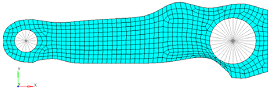
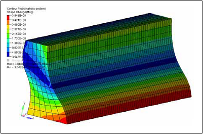
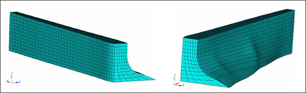
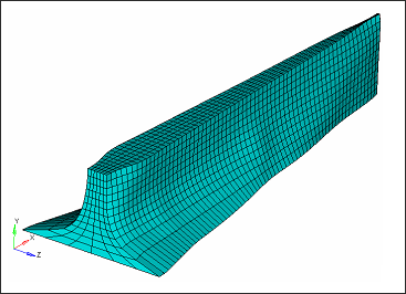
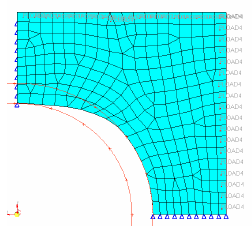
DTYPE has three distinct options:
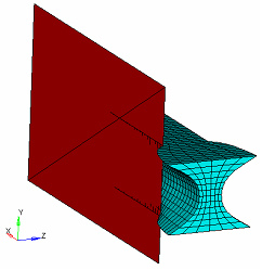
| 1. | GROW – grids cannot move inside of the initial part boundary. |
| 2. | SHRINK – grids cannot move outside of the initial part boundary. |
| 3. | BOTH – grids are unconstrained. |
|
|
|
GROW
|
SHRINK
|
BOTH
|

|
Undeformed
|

|
Deformed
|
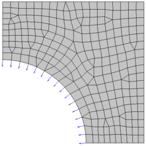
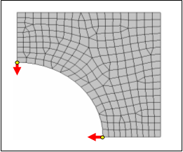
Move Factor
The maximum allowable movement in one iteration of the grids defining a free-shape design region is specified as:
MVFACTOR * mesh_size
where, "mesh_size" is the average mesh size of the design region defined in the same DSHAPE card.
MVFACTOR is defined on the PERT continuation line of the DSHAPE entry.
(1)
|
(2)
|
(3)
|
(4)
|
(5)
|
(6)
|
(7)
|
(8)
|
(9)
|
(10)
|
|
PERT
|
DTYPE
|
MVFACTOR
|
NSMOOTH
|
MXSHRK
|
MXGROW
|
SMETHOD
|
NTRANS
|
|
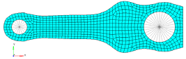
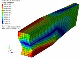
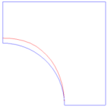
The default value of MVFACTOR is 0.5. A smaller MVFACTOR will make free-shape optimization run slower but with more stability. Conversely, a larger MVFACTOR will make free-shape optimization run faster but with less stability.
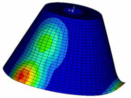
MVFACTOR affects the maximum movement in one iteration.

|
Undeformed shape
|

|
Shape at iteration 1 with MVFACTOR = 0.5 (default)
|

|
Shape at iteration 1 with MVFACTOR = 1.0
|
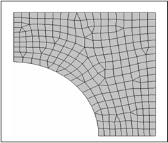
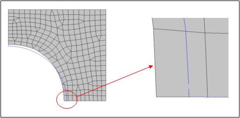
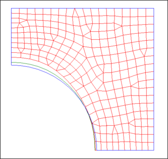
Number of Layers for Mesh Smoothing
With free-shape optimization, internal grids adjacent to those grids defining the design region are moved to avoid mesh distortion. The number of layers of grids to be included in the mesh smoothing buffer may be defined by the NSMOOTH field on the PERT continuation line of the DSHAPE entry.
(1)
|
(2)
|
(3)
|
(4)
|
(5)
|
(6)
|
(7)
|
(8)
|
(9)
|
(10)
|
|
PERT
|
DTYPE
|
MVFACTOR
|
NSMOOTH
|
MXSHRK
|
MXGROW
|
SMETHOD
|
NTRANS
|
|
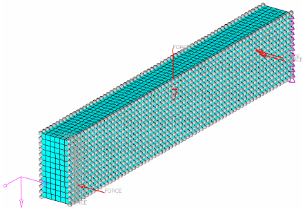
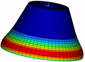
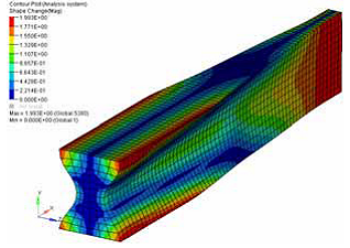
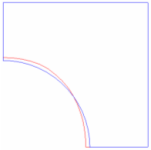
The default value of NSMOOTH is 10. A larger NSMOOTH will give a larger smoothing buffer, and consequently will work better in avoiding mesh distortion; however, it will result in a slower optimization.
|
|
NSMOOTH=5, 5 layers of grids move along with the design boundary.
|
NSMOOTH=1, only 1 layer of grids move along with the design boundary.
|
Maximum Shrinkage and Growth
The maximum shrinkage and growth provide a simple way to limit the total amount of deformation of the free-shape design region. These parameters are defined on the PERT continuation line of the DSHAPE entry.
(1)
|
(2)
|
(3)
|
(4)
|
(5)
|
(6)
|
(7)
|
(8)
|
(9)
|
(10)
|
|
PERT
|
DTYPE
|
MVFACTOR
|
NSMOOTH
|
MXSHRK
|
MXGROW
|
SMETHOD
|
NTRANS
|
|
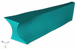
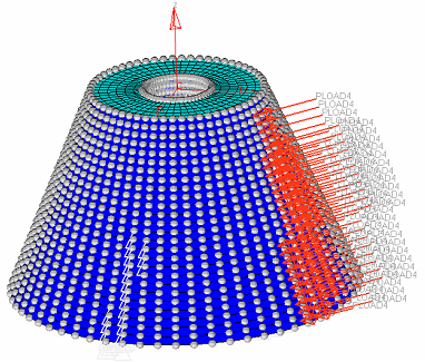
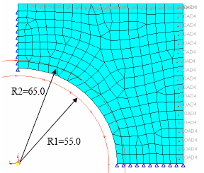
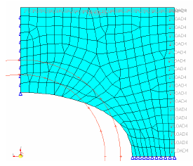
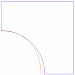
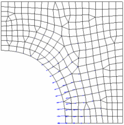
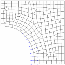
The design region is offset to form two barriers; MXSHRK is the offset in the shrinkage direction and MXGROW is the offset in the growth direction. The design region is then constrained to deform between these two barriers.
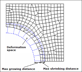
Deformation space defined by the maximum growing/shrinking distance
For more details and an example, refer to the section on the Mesh Barrier Constraint below.
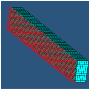
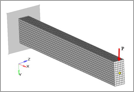
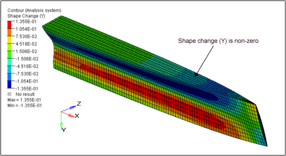
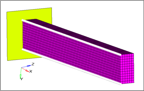
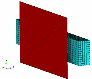
Additional treatment to grids in the Transition Zone
When the entire surface or edge of a system is not a design zone and both design and non-design regions exist adjacent to one another, a transition zone can be defined using NTRANS which helps to smooth out the transition. Sharp changes can occur in the design region during optimization and the sections of the design region closest to the non-design region are designated as a transition zone where the corresponding location of the adjacent non-design region is taken into consideration allowing for a smoother transition from the design to non-design region.
NTRANS defines the number of design grid layers in the transition zone to non-design area, where additional treatment will be applied to produce smooth transition.
(1)
|
(2)
|
(3)
|
(4)
|
(5)
|
(6)
|
(7)
|
(8)
|
(9)
|
(10)
|
|
PERT
|
DTYPE
|
MVFACTOR
|
NSMOOTH
|
MXSHRK
|
MXGROW
|
SMETHOD
|
NTRANS
|
|
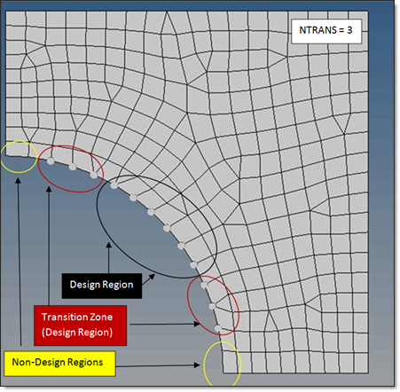
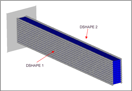
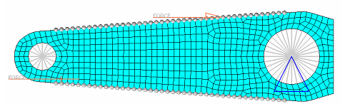
Defining the Transition Zone grid points for a smooth transition between Design and Non-Design regions (NTRANS=3)
The resulting optimized design will incorporate the effect of non-design regions while moving the transition zone grid points to achieve a smoother final design. The three regions illustrated in the figure above consist of the following highlighted nodes:
| • | The non-design nodes (marked by yellow circles), which do not move during Freeshape optimization. |
The design nodes are separated into two groups:
- Design nodes in transition zone (highlighted nodes enclosed by red circles, defined by NTRANS=3)
- Design nodes that are NOT in the transition zone (highlighted nodes enclosed by a black circle)
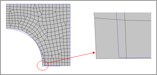
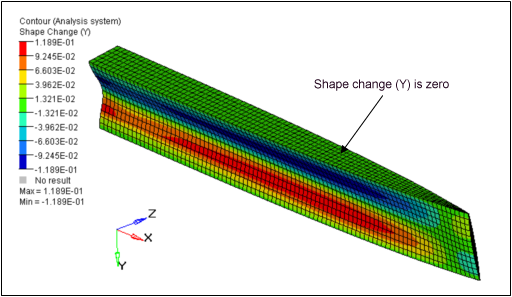
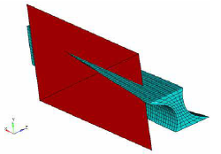
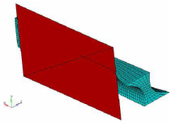
The design nodes in the transition zone will be adjusted during Free-shape optimization to build a smooth transition between “(1) non-design nodes” and “(3) Design nodes that are NOT in the transition zone”. Otherwise, discontinuous or sharp sections may occur, which is explained in the illustration below.
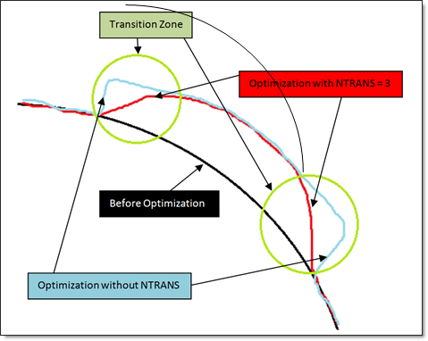
Defining the Transition Zone grid points for a smooth transition between Design and Non-Design regions (NTRANS=3)
|