|
»Click here to display Table of Contents«
|

DVGRID |

|

|

|

|
|
DVGRID |
|
|

|

|
|
»Click here to display Table of Contents«
|
DVGRID |
|
|
|
|
|
DVGRID |
|
|
|
|
Bulk Data Entry
DVGRID – Relationship between Design Variable and Grid Point Location
Description
Defines the relationship between a design variable and a grid point location.
Format
(1) |
(2) |
(3) |
(4) |
(5) |
(6) |
(7) |
(8) |
(9) |
(10) |
DVGRID |
DVID |
GID |
CID |
COEFF |
X |
Y |
Z |
|
|
|
Field |
Contents |
DVID |
DESVAR identification number. (Integer > 0) |
GID |
GRID identification number. (Integer > 0) |
CID |
Coordinate system identification number. A CID of zero or blank references the basic coordinate system. Default = 0 (Integer > 0) |
COEFF |
Multiplier to the vector defined in fields 6, 7, and 8. |
X, Y, Z |
Components of the vector defining the perturbation of the grid in the coordinate system defined by CID. |
| 1. | Multiple references to the same grid ID will yield a summation of perturbation vectors for the given grid. |
| 2. | The DVGRID data defines perturbations in the locations of the grids. The updated location of the grid is: |
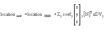
Where, DVj is the value of design variable j and [N]T is the coordinate transformation matrix based on the CID and the GRID location.
| 3. | The OUTPUT, DVGRID option creates shape variable definitions for displacement or eigenvector results of linear static, normal modes, or linear buckling analyses. These shape variable definitions can then be used in subsequent optimizations. This process facilitates the use of "natural" shape functions. |
| 4. | This card is represented as an optimization design variable in HyperMesh. |
See Also: