|
»Click here to display Table of Contents«
|

Example 1 - Twisted Beam |

|

|

|

|
|
Example 1 - Twisted Beam |
|
|
|

|
|
»Click here to display Table of Contents«
|
Example 1 - Twisted Beam |
|
|
|
|
|
Example 1 - Twisted Beam |
|
|
|
|
This example deals with a clamped beam subjected to a coupled torsion-bending loading. This simple test being particularly severe for shell elements, a sensitivity study is performed on the mesh and element formulation. An analytical solution validates the accuracy of results. The problem under analysis consists of a concentrated load being applied to the extremity of the beam with the static approach requiring a convergence method to enable fast convergence towards equilibrium. The dynamic relaxation option allows for an efficient quasi-static response to be obtained.
The results are compared using two separate views:
| • | Shell element formulations (BATOZ, QEPH, DKT18 and BT hourglass type 4). |
| • | Influence of the mesh (Triangular and quadrilateral meshes are compared using three different element densities: 4x24, 2x12 and 1x3). |
Several results can be extracted:
| • | X-displacement of the loaded point |
| • | Y-displacement of the loaded point |
| • | Z-displacement of the loaded point |
| • | Error on energy |
| • | CPU time |
Comparisons are made between theoretical displacements and those by simulations.
Results show that QEPH and BATOZ element formulations provide the most accurate results and the more the mesh is fine, the more accurate the results will be. To pass this test, a good curvature representation of element formulation is needed; the BT hourglass type 4 formulation does not satisfy this condition. QEPH offers a good ratio in terms of precision-cost, and is useful for quasi-static analysis. DKT18 is a costly element formulation.
TitleTwisted beam |
|
||||||||
Number1.1 |
|||||||||
Brief DescriptionBending test on a twisted beam modeled with triangular and quadrilateral meshes and different element formulations (QEPH, BT hourglass type 4, BATOZ, DKT). |
|||||||||
Keywords
|
|||||||||
RADIOSS Options
|
|||||||||
Compared to / Validation Method
|
|||||||||
Input FileQEPH: <install_directory>/demos/hwsolvers/radioss/01_Twisted_Beam/QEPH/TWISBEAM* BATOZ: <install_directory>/demos/hwsolvers/radioss/01_Twisted_Beam/BATOZ/TWISBEAM* BT-TYPE4: <install_directory>/demos/hwsolvers/radioss/01_Twisted_Beam/BT-type4/TWISBEAM* DKT18: <install_directory>/demos/hwsolvers/radioss/01_Twisted_Beam/DKT18/TWISBEAM* |
|||||||||
Technical / Theoretical LevelMedium |
|||||||||
The purpose of this example is to compare element formulations concerning mesh density with regard to a coupled torsion-bending problem.
Units: In, s, lbs-s2/in
A twisted beam is clamped at one end, and subjected to a concentrated load at the other end.
The material used follows a linear elastic law (/MAT/LAW1) and has the following geometrical characteristics with no specific measurement unit:
Initial density: 7.34x10⁻⁴
Young’s modulus: 2.9x10⁷ [MPA]
Poisson ratio: 0.22
Thickness: 0.32
Length: 12
Width: 1.1
Load case:
Fx = 0
Fy = 1.0
Fz = 0
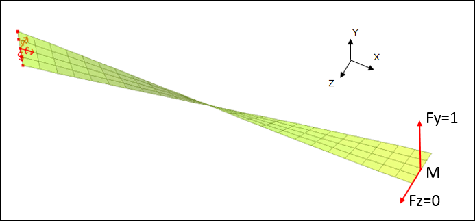
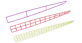
Fig 1: Initial mesh (4x24).
This simple test is particularly severe for shell element behaviors, due to the torsion-bending coupling. Users appreciate the qualities/restrictions of the shell element formulations in RADIOSS.
The following points are:
| • | Displacements are very low. Thus, you are faced with a linear problem. |
| • | Another load case, using Fy = 0 and Fz = 1, is considered, but does not give concern to additional conclusions. |
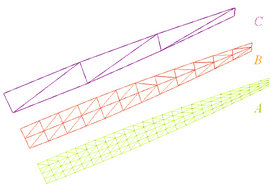
The beam is modeled with 4-node shell and 3-node shell meshes.
The following are tested for each model:
| • | Four shell formulations: |
- QEPH formulation (4-node shell element, Ishell = 24)
- BT (Hourglass type 4) formulation (4-node shell element, Ishell = 4)
- QBATOZ formulation (4-node shell element, Ishell = 12)
- DKT18 formulation (3-node shell element, Ish3n = 30)
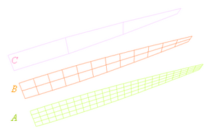
| • | Three mesh densities in each shell formulation: |
- Mesh A: 4 x 24 elements
- Mesh B: 2 x 12 elements
- Mesh C: 1 x 3 elements
4-node Shell Mesh |
3-node Shell Mesh |
|---|---|
|
|
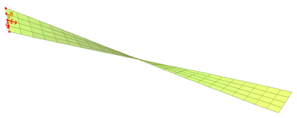
One concentrated load is applied at the extremity, on central node M (for mesh A and mesh B), two concentrated loads must be applied to the corner points of the beam end (for mesh C).
A static solution provides the steady state part of the transient response. In this example, dynamic relaxation is used to obtain a static result. Static loading is considered a dynamic resolution method. Using /DYREL in the *_0002.rad file, the dynamic loading is damped by introducing a diagonal damping matrix.
Relaxation factor = 1; period to be damped = 0.0025
The displacement of node M is stabilized at the static response: t = 0.035.
For further details, refer to the RADIOSS Theory Manual.
The displacement components regarding X, Y and Z of node M are compared to the beam theory in order to understand the performance of the various elements when several mesh densities are used.
Reference results [Batoz & Dhatt, "Structural Modeling Finite Elements", Vol. 3, Hermès, Paris, 1992]:
X-displacement: UM = 0
Y-displacement: VM = 0.00175
Z-displacement: WM = -0.00179
The chart below shows the displacement oscillations of point M until reaching stabilization in the direction of the static solution.
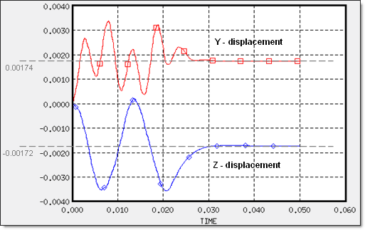
Fig 2: Time history plots of point M displacements (Mesh A/QEPH)
| • | Energy margin error at t = 0.05: |
|
QEPH |
BT (type 4) |
BATOZ |
DKT18 |
|---|---|---|---|---|
Energy margin error |
0.1% |
99.9% |
0% |
0% |
| • | CPU (normalized): |
|
QEPH |
BT (type 4) |
BATOZ |
DKT18 |
|---|---|---|---|---|
CPU |
1 |
diverge |
1.1042 |
1.1430 |
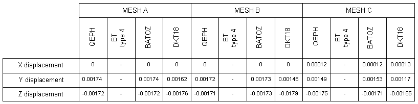
| • | Nodal displacements of node M: |
| • | Ratio (Displacement by simulation/ Displacement by theory): |
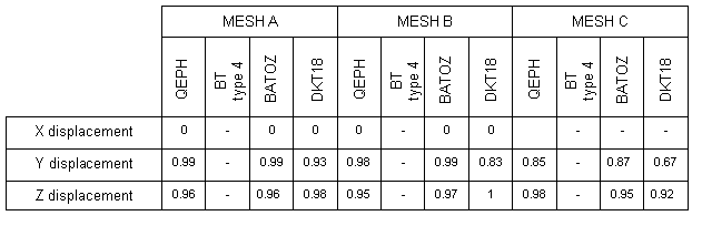
| • | QBAT and QEPH provide good results (precision). |
| • | Good results provided by DKT18 when the mesh is fine, though no better than QBAT and QEPH. |
| • | BT (Hourglass type 4) does not pass this test (due to the flat facet approach). |
| • | QEPH: the best element formulation for quasi-static analysis. Very good precision-cost ratio. |
| • | QBAT: good curvature representation. For quasi-static analysis, the cost is 4% higher compared to using the QEPH formulation. |
| • | DKT18 represents the highest cost for this test. |