Definition
This option is used to simulate chambered airbags and may be used to unfold an airbag.
Each COMMU1 type monitored volume works like an AIRBAG1 type monitored volume with possible vent communication with some other COMMU1 type monitored volume. A chambered airbag is therefore designed with two or more COMMU1 type monitored volumes.
Each monitored volume can have an inflator and vent holes.
Case 1: Folded Airbag
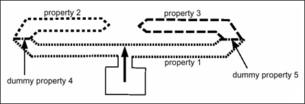
To model a folded airbag, one COMMU1 type monitored volume is used for each folded part. The boundary between two folded parts is closed with a dummy property set. The area of communication is defined with this dummy property set. The pressure in each folded part will be different and the area of communication will increase during inflation. With this modelization the volume with inflator will inflate first and before the folded parts.
| Volume 1: Prop. 1 + 4 + 5 | Communication area: vol. 1 to 2: prop. 4 |
vol. 1 to 3: prop. 5
| Volume 2: Prop. 2 + 4 | Communication area: vol. 2 to 1: prop. 4 |
| Volume 3: Prop. 3 + 5 | Communication area: vol. 3 to 1: prop. 5 |
Case 2: More General Use
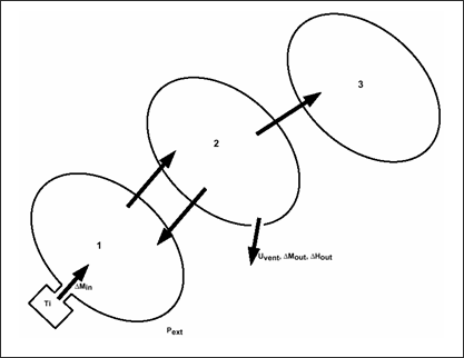
Monitored volume 1 can communicate with monitored volume 2 with or without communication from 2 to 1. Communication area, deflation pressure or time from 1 to 2 can be different than corresponding values from 2 to 1. That way it is possible to model a valve communication.
Two communication monitored volumes can have common nodes or common shell property set, but this is optional.
Volume 1 communicates with volume 2, and volume 2 with volume 1 and 3, but there is no communication from 3 to 2.
General Equations
Same equations for AIRBAG type monitored volume are used, but incoming and outgoing enthalpy and kinetic energies will take into account the communicating bags. For each communicating volume for which pressure is lower than in current volume, a mass and energy flow is computed with same equations for vent holes, the external pressure is just replaced by the pressure of communicating volume:
with,

These mass and energy fluxes are removed from current volume and added to communicating volume at the next cycle.
Inflator, Vent Hole, Initial Conditions
Inflator, atmospheric vent holes and initial conditions are identical to /MONVOL/AIRBAG1 type monitored volume.
Specific Input
The specific input for this type is:
 is perfect gas constant
 is viscosity factor
Pext is external pressure
 is relative vent deflation pressure
Avent is vent area (Ipvent = 0) or discharge factor (Ipvent  0)
0)
Tvent is time to deflate vent hole
fct_IDmas is injected mass curve (or mass rate)
Fscalemas is scale factor for injected mass curve (or mass rate)
fct_IDT is injected temperature curve
FscaleT is scale factor for injected temperature curve
sens_ID is sensor number to start injection
Ipvent is property set number defining vent hole
Cp is specific heat at constant pressure
Nca is the number of communicating volume
For each communicating volume (1 to Nca):
id is the identification of communicating volume
Ip com is the property set number defining communication area
 is the relative communication deflation pressure
Acom is the communication area (Ip com = 0) or discharge factor (Ip com 0)
Tcom is the time to deflate communication area
In volume j input, the data for communication with volume k concerns only the flow from j to k. The data concerning the flow from k to j is defined in volume k input.
See Also:
Theory Manual


