AIRBAG1 Type Monitored Volume |

|

|

|

|
|
AIRBAG1 Type Monitored Volume |

|

|

|

|
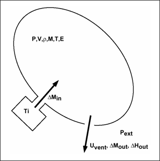
A uniform pressure is assumed inside the volume. Perfect gas law and adiabatic conditions are assumed. Injected mass (or mass flow rate) and temperature are defined as a time function. A sensor can define the inflator starting time.
Deflation of the vent hole is available after reaching a pressure (Pdef) or time (tdef) criteria.

A viscosity, ![]() can be used to reduce numerical oscillations.
can be used to reduce numerical oscillations.
If ![]() = 1, a critical damping (shell mass and volume stiffness) is used. A viscous pressure, q is computed as:
= 1, a critical damping (shell mass and volume stiffness) is used. A viscous pressure, q is computed as:
![]()
![]()
Where, t is the fabric thickness, ![]() is the density of the fabric, and A is the bag surface.
is the density of the fabric, and A is the bag surface.
The applied pressure is:
![]()
To avoid initial disequilibrium and mathematical discontinuity for zero mass or zero volume, the following initial conditions are set at time zero (Iequi =0) or at the beginning of jetting (if Iequi =1).
| • | Pext = Pini external pressure |
| • | T0 = Tini initial temperature (295°K by default) |
| • | If the initial volume is less than 10-4 A3/2, a constant small volume is added to obtain an initial volume: Vini = 10-4 A3/2 |
| • | Initial mass, energy and density are defined from above values. |
There is no need to define an injected mass at time zero.
| 1. | Initial gas |
![]() is the initial gas constant at initial temperature
is the initial gas constant at initial temperature
![]() =
= ![]()
Where, R is the universal gas constant depending on the unit system (R=8.3144 Jmole-1K-1 ), and M is the molecular weight of the initial gas cpa, cpb, and cpc specific heat coefficients of the following equation, defining the specific capacity per unit mass at constant pressure for the initial gas:
![]()
| 2. | Injected gas |
“Njet” defines the number of injector by monitored volume
![]() is the injected gas constant at initial temperature
is the injected gas constant at initial temperature
cpa, cpb, and cpc are specific heat coefficients corresponding to the injected gas
fct_lDmas is the injected mass curve
Fscalemas is the scale factor for injected mass curve
fct_IDT is the injected temperature curve
FscaleT is the scale factor for injected temperature curve
Injected mass curve and injection temperature can be obtained:
| • | from the airbag manufacturer |
| • | from a tank test |
sens_ID is the sensor number to start injection
| 3. | Jetting effect (only for /MONVOL/AIRBAG1 or /MONVOL/COMMU1) |
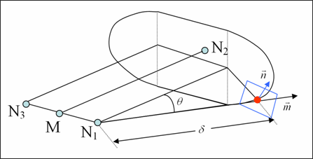
Ijet, if Ijet ![]() 0, the jetting effect is modeled as an overpressure
0, the jetting effect is modeled as an overpressure ![]() applied to elements of the bag, as shown below.
applied to elements of the bag, as shown below.
![]()

N1, N2, and N3 are defined by you in correspondence with the injector geometry (see RADIOSS Starter Input Manual).
![]() are empiric functions provided by you.
are empiric functions provided by you.
Nvent defines the number of vent holes used.
Idvent is the surface identifier defining vent hole
Avent is the vent area (if Idvent = 0) or a scale factor (Idvent ![]() 0)
0)
Bvent equals 0 (if Idvent = 0) or a scale factor on impacted surface (Idvent ![]() 0)
0)
Tstop is a stop time for venting
Tvent is the time at which leakage starts
![]() is the relative vent deflation pressure
is the relative vent deflation pressure
![]() is the time duration during which
is the time duration during which ![]()
![]() is the function identifier
is the function identifier ![]() for Chemkin model
for Chemkin model
![]() is the scale factor on
is the scale factor on ![]()
If ![]() , the outflow velocity,
, the outflow velocity, ![]() is defined by Chemkin as:
is defined by Chemkin as:
![]()
and the outgoing mass is computed as:
![]()
or, with conservation of enthalpy between airbag and vent hole, adiabatic conditions and unshocked flow, it is then possible to express outgoing mass flow through vent holes as a function of Pext, ![]() , Pvent, uvent and Avent.
, Pvent, uvent and Avent.

In the case of supersonic outlet flow, vent pressure, Pvent is equal to external pressure, Pext for unshocked flow. For shocked flow, Pvent is equal to critical pressure, Pcrit and velocity, u is bounded to critical sound speed:

and

![]()
The outgoing mass flow of gas i is:

Where, V(i) is the volume occupied by gas i and satisfies:

then:

The isenthalpic model is also used for porosity. In this case, you can define the surface for outgoing flow with the following equation:
![]()
Where, A is the area of the specified surface, l is the scale factor, P is the pressure of the gas, and t is the time.
It is also possible to define closure of the porous surface in the case of contact (see Ibag flag in interface type 7).
See Also: