MBD system level responses can be displacement, velocity, acceleration, force, or some predefined function of those four quantities. MBD system level responses can be optimized/constrained along with other structural responses of flexible bodies in MBD systems.
The example shown here is intended to minimize the mass of a system. Constraints are imposed on the stress of a flexible body and the velocity of a point. Notable points are shown below.
System Level Responses
In order for the system level responses to be made available to the optimization process, MBREQE or MBREQM entries must be defined so that the MBD solver can generate the appropriate output.
$------|--MID--|--GID--|
MARKER 55 9929617
$------|--RSID-|--RID--|--ITEM-|--MID--|
MBREQM 99 999 VEL 55
Then RID (999 in this case) must be referenced in DRESP1.
$------|-------|-------|-------|-------|-------|-------|-------|-------|
DRESP1 3 VELO MBVEL MBREQM TX MIN 999
It is not necessary to reference the requests defined by MBREQM/E in the subcase to make the requested responses available for the optimization. RSID (99 in this case) of MBREQM can be an arbitrary positive integer.
DVGRID Including Joint Location
Changing the length of a body is a common method of achieving desired system level responses. This change in shape can be defined using DVGRIDs. In this case, the DVGRIDs need to be defined carefully, as it is necessary to ensure that the joints remain in a valid configuration while changing the length of the bodies.
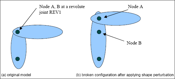
A common mistake in defining shape change that involves change of joint locations
In the figure above, Nodes A and B must remain coincident after applying the shape perturbation.
The correct configuration after applying shape perturbation vector should be:
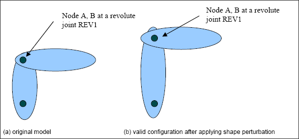
Correct way of defining shape change that involves change of joint locations
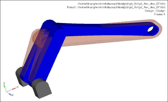
The input file for this problem can be found at <install_directory>/altair/demos/hwsolvers/optistruct/mbdsystemlvlopt.fem.
The optimization result should look like the following. The opaque orange was the base line model and blue one is optimized model.