|
»Click here to display Table of Contents«
|

Multi-Domain Technique |

|

|

|

|
|
Multi-Domain Technique |
|
|
|

|
|
»Click here to display Table of Contents«
|
Multi-Domain Technique |
|
|
|
|
|
Multi-Domain Technique |
|
|
|
|
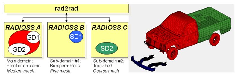
The objective of the Multi-Domain technique (also referred to as RAD2RAD) is to optimize the computing performances of large scale RADIOSS models that meet certain criteria:
| • | Possibility of sub-dividing the whole model into a number of distinct subdomains with clearly defined interfaces/connections between them. |
| • | Different subdomains should be characterized by different mesh sizes and consequently very different minimal time step. |
The goal is to improve prediction accuracy at reasonable, possibly advantageous, computation time for models with domains of very different time step sizes.
For example, it is appealing to use Multi-Domain technique to compute large models that have one or more parts finely meshed to capture specific local phenomena such as cracks localization/propagation.
It is even more appealing to use Multi-Domain technique to compute large fluid-structure interaction models, as in aircraft ditching or landing simulations, where fluid elements with high time steps are numerous compared to Lagrange structure elements with very small time steps.
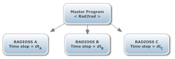
In the explicit integration scheme used by RADIOSS crash solver, the time step of the global model is penalized by the elements having the smallest time step. The concept is to replace this global model with physically equivalent subdomains, separating parts with different minimal time step. Each subdomain is resolved as a distinct RADIOSS model using its own time step, the force and momentum transfers between them being calculated by a separate master program (RAD2RAD), assuring stability constraints.
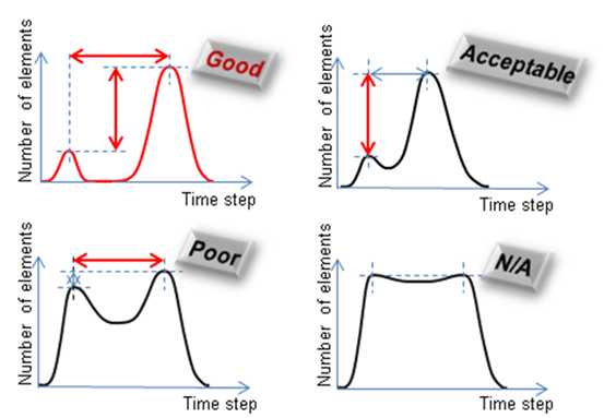
Multi-Domain efficiency is based on two types of discrepancies outlined below:
| • | time step sizes |
| • | domains relative sizes |
It is particularly adapted to models with main and subdomains:
| • | of very different mesh densities hence very different time steps |
| • | of different formulations like Lagrange, ALE or Lagrange, and SPH, provided the ALE or SPH domain is larger than the Lagrange domain |
This efficiency of the multi-domain method can be measured by the speedup coefficient. That is the ratio between the elapsed time of the original computation and the elapsed time obtained with the multi-domains method.
If the CPU cost of the master program (RAD2RAD) and time spent in communications are negligible, and that the time step and the cost per cycle of each domain are constant during the computation, an estimation of the speedup can be computed in order to determine if the use of multi-domains is relevant or not.
In the case of 2 domains, A and B, A being the domain with the smallest time step, the speedup can be obtained using the following formula:
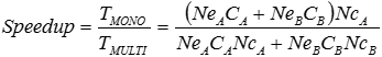
Where, Nc is the number of cycles for each domain, Ne is the number of elements of each domain, and C is the average cost per element and per cycle for each domain.
The formula can be rewritten as:
![]()
Where,
![]() is the average cost per cycle ratio between domains
is the average cost per cycle ratio between domains
![]() is the time step ratio
is the time step ratio
![]() is the percentage of elements in the domain with the smallest time step
is the percentage of elements in the domain with the smallest time step
If the average cost per cycle is the same in the 2 domains then the formula becomes:
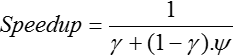
Therefore, the speedup is very high when ![]() and
and ![]() are close to zero, meaning that domain A is small compared to B and time step ratio is high. This is what is depicted in the previous illustration.
are close to zero, meaning that domain A is small compared to B and time step ratio is high. This is what is depicted in the previous illustration.
The two possible model setups are:
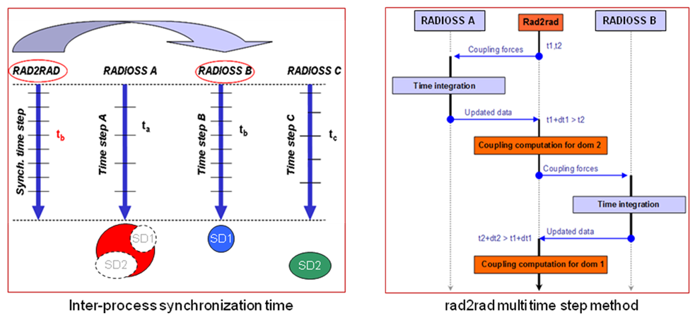
The RADIOSS runs are completely independent and do not communicate directly with each other. Each subdomain uses its own time step as outlined below:
The time step of each subdomain is arbitrary; but to allow the best gain in terms of speedup they should be significantly different from each other.
The best manual decomposition will be obtained by dividing global model into parts with a large number of elements having a big time step on one side, and a small number of elements with small time step on the other side.
All communication, data transfers, time step synchronization, equilibrium and stability conditions on the domain frontiers are assured by the master program.
As of 14.0, Fluid Structure Interaction simulations, including ALE and/or SPH are possible.
As of 13.0, Multi-Domain is fully Hybrid-MPP compatible, i.e. enabling multiple threading for RAD2RAD.
For better computational performances:
| • | The subdomain should be less than 30% of the full domain (main _ sub-domains) in terms of nodes or elements and the natural (or acceptable mass scaling) time step ratio between subdomain and main domains should be below 1/3. |
| • | Apply the same rule for pure Lagrange or FSI models, which is to put the parts with a significantly smaller time step in the subdomain. |
| • | For pure Lagrange Multi-Domain models, the RAD2RAD workload must be minimized as much as possible by reducing the communication flow between domains, with this aim, contact interfaces and connections between sub and main domains should be minimized as much as possible. |
| • | It is important to check that the subdomain is not part of a global contact interface, but has its own subdomain self-impact and to create cross domain contacts not larger than needed. |
| • | It is strongly recommended to symmetrize each created cross domain contact interfaces. |
| • | For Multi-Domain with ALE or SPH, there is no need to minimize the contact interfaces between fluid and structure. |
| • | For models with a subdomain having a relatively small amount of elements, the number of allocated CPU should respect the empirical rule of at least 2000 element per CPU and it is advised to use the maximum possible number of threads per node of the used cluster. |
| • | In one model, scattered parts with low time steps do not necessarily justify multiple subdomains. If these parts have similar low time steps, they must be put into one subdomain. |
| • | If connections between subdomains and main domains also have a small time step, these connections should be part of the subdomain. |
| • | Subdomains essentially composed of Lagrange 3D elements, make the Multi-Domain less efficient than if it was composed of 2D and 1D elements. |
| • | For Multi-Domain FSI, it is advised to use the main domain as an elementary free time step with a scaling factor of 0.5 for ALE and a nodal free time step with a scaling factor of 0.6. |