This tutorial illustrates Follower Loads setup, and the usage of Nonlinear Adaptive Criteria (NLADAPT) and how intermediate results can be requested for Nonlinear runs. You will see how the activation of Follower Loads leads to a significant difference in model behavior and results, and how inaccurate results may be output if the follower load mechanism is not taken into account. You will look at activation of Follower Loads that are concentrated forces (Beam model) and of Follower Loads that are pressures (Rubber Disk model).
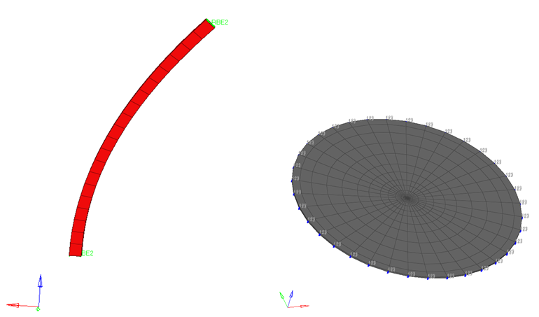
Figure 1: Illustration of the models: Follower Loads: Concentrated Forces – Beam (left), Pressures – Rubber Disk Model (Right).
Summary
Beam Model
The model is a curved steel beam constructed with CHEXA elements. A Force of 100 N is applied to the top cross-section of the beam. The bottom of the beam is constrained by single point constraints (SPC).
The following exercises are included:
| • | Launch HyperMesh and importing the model |
| • | Run the model without Follower Load activation |
| • | Activate Follower Load (Concentrated force) |
| • | Learn how to adjust nonlinear adaptive criteria (NLADAPT) |
| • | Request intermediate nonlinear results using NLOUT. |
| • | Review and compare results with and without follower loads. Also visualize the correct animation of the deforming model as a result of NLOUT activation. |
Rubber Disk Model
The model a rubber disk constructed with MATHE elements. A pressure load of 1 N/mm2 is applied to the rubber disk. The circumference of the disk is constrained via single point constraints (SPC).
The following exercises are included:
| • | Launch HyperMesh and importing the model |
| • | Run the model without Follower Load activation |
| • | Activate Follower Load (Pressure load) with Option=1, Option=2, and Option=3 |
| • | Request intermediate nonlinear results using NLOUT. |
| • | Review and compare results with and without follower loads. Also visualize the correct animation of the deforming model as a result of NLOUT activation. |
Prerequisites
| 1. | The latest version of HyperMesh, HyperView and OptiStruct software installations. Some of the presented features are available only in HyperMesh, HyperView, and OptiStruct version 14.0.130/14.0.230 or later. |
| 2. | The solver decks beam_fllwer.fem and disk_fllwer.fem are located in the optistruct.zip file. Refer to Accessing the Model Files. |
Setting up the Beam model in HyperMesh
Step 1: Selecting the OptiStruct User Profile and loading the model into HyperMesh
| 2. | Select OptiStruct in the User Profiles dialog. |

Figure 2: Selecting the OptiStruct User Profile
This loads the OptiStruct user profile. It includes the appropriate template, macro menu, and import reader, paring down the functionality of HyperMesh to what is relevant for generating models for OptiStruct.
The User Profiles dialog can also be accessed from the Preferences menu on the toolbar.
| 4. | Click the Import Solver Deck panel toolbar icon  and browse to the location that contains the model. and browse to the location that contains the model. |
| 5. | Select the beam_fllwer.fem file you saved to your working directory from the optistruct.zip file. Refer to Accessing the Model Files. |
The model is now loaded into HyperMesh.
Step 2: Running the beam model without Follower Load activation
The imported model already contains the material, the property, the boundary conditions, activation of large displacement, and the loadstep. In this step, you will run the model directly to generate results.
| 1. | From the Analysis page, select the OptiStruct panel. |
| 2. | Click save as following the input file: field. |
A Save As window opens.
| 3. | Select the directory where you want to write the OptiStruct model file. |
| 4. | For File name, enter beam_fllwer.fem. The .fem filename extension is the recommended extension for OptiStruct input decks. |
The name and location of the beam_fllwer.fem file displays in the input file: field.
| 6. | Set memory options: to memory default. |
| 7. | Set run options: to analysis. |
| 8. | Set export options: to all. |
This launches the job.
If the job is successful, the new results files will appear in the directory from which beam_fllwer.fem was selected. Look in the beam_fllwer.out file for error messages that could help debug the input deck, if any errors are present.
Step 3: Activating Follower Loads for the beam model
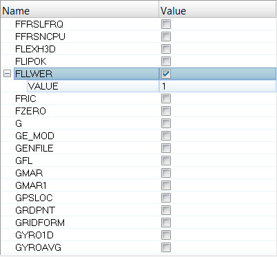
Follower loads for concentrated forces do not depend on the area of the element face to whose grids they are applied. Therefore, the results will remain the same for any activation option chosen on either the FLLWER bulk data entry or the PARAM,FLLWER entry. Since you only have one subcase, select the parameter PARAM,FLLWER to activate follower loading for this model.
| 1. | In the Model browser, click PARAM. The list of parameters will show up in the Entity Editor below. |
| 2. | Check the box next to FLLWER. A VALUE field displays below. |
| 3. | Click on the field next to VALUE and select 1 from the drop-down menu to activate Follower Loads. As mentioned in the beginning of this step, the options 1, 2, and 3 have the same effect for concentrated loads since element face areas are not involved. Using the parameter instead of the Bulk Entry activates follower loading for all subcases in a model. If you want to only activate follower loads for specific subcases, you can use FLLWER Bulk Data and Subcase entries. |
Step 4: Activating Nonlinear Adaptive Criteria (NLADAPT)
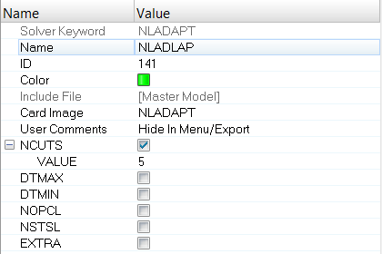
Parameters that allow you to define Nonlinear Adaptive Criteria are available via the NLADAPT Bulk Data and Subcase entries. You can typically specify time-stepping and convergence criteria for Nonlinear Analysis if you run into convergence issues. Refer to the NCUTS parameter in this exercise. Similarly, you can define DTMIN, and DTMAX parameters, some of the other parameters like NOPCL and NSTSL are intended for models with contacts.
| 1. | Right-click in the Model browser, click Create > Load Collector from the drop-down menu. |
| 2. | Name the load collector NLADAPT. |
| 3. | In the corresponding Entity Editor, click on the field next to Card Image and select NLADAPT. |
| 4. | Activate the check box next to NCUTS and in the VALUE field enter the integer 5 (which is the default). This indicates to OptiStruct that the maximum number of cutbacks allowed to reduce the time increment is 5. OptiStruct will error out if a greater number of cutbacks is required for a particular time increment for iterative convergence. |
| 5. | Click on the Nonlinear Static Load Step to open it in the Entity Editor. |
| 6. | Click on the field next to NLADAPT and on the yellow Loadcol button. |
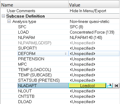
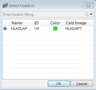
| 7. | Select the NLADAPT load collector in the Select Loadcol dialog and click OK. |
Step 5: Activating Nonlinear Intermediate Results (NLOUT)
Parameters that allow you to activate Nonlinear Intermediate Results are available via the NLOUT Bulk Data and Subcase entries. The number of intervals at which intermediate results are output is controlled by the NINT parameter. The SVNONCNV parameter can be used to activate/deactivate the output of results for non-convergent solutions. This is currently turned on by default (set to YES).
| 1. | Right-click in the Model browser, click Create and select Load Collector from the drop-down menu. |
| 2. | Name the load collector NLOUT. |
| 3. | In the corresponding Entity Editor, click on the field next to Card Image and select NLOUT. |
| 4. | Activate the check box next to NINT and in the VALUE field enter the integer 10 (which is the default). This indicates to OptiStruct that the maximum number of intervals at which intermediate results are requested is 10. If the load increment from any load “n” to load “n+1” is greater than 1/NINT (in this case, 1/10 is 0.1), then the results corresponding to load level “n+1” are saved for output; otherwise, the results are not saved. |
Note that this parameter has no control over the adaptive load size selection during the incremental-iterative solution process. It only specifies the number of intervals when results are saved for output during the solution process.
| 5. | Click on the Nonlinear Static Load Step to open it in the Entity Editor. |
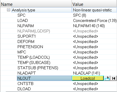
| 6. | Click on the field next to NLOUT and on the yellow Loadcol button. |
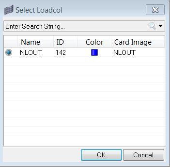
| 7. | Select the NLOUT load collector in the Select Loadcol dialog and click OK. |
Step 6: Running the Beam model with Follower Loads activation
The model now consists of loads which have been identified as follower loads. Additionally, you have learned how to activate adaptive criteria for nonlinear analysis, and request results at intermediate increments.
| 1. | Follow the instructions provided in Step 2 to save and launch OptiStruct. |
| 2. | For File name, enter beam_fllwer_ON.fem. |
If the job is successful, the new results files will appear in the directory from which beam_fllwer_ON.fem was selected. Look in the beam_fllwer_ON.out file for error messages that could help debug the input deck, if any errors are present.
Viewing and Post-processing the Results for the Beam Model
Displacements and Element Stresses are calculated by default and can be plotted using the Contour panel in HyperView.
Step 7: Comparing the Displacement Results between models with and without Follower Load activation
| 2. | Select the page window layout icon  to split the page into two windows. to split the page into two windows. |
| 3. | In the first window, load the beam_fllwer.h3d file by clicking  and navigating to your working directory. and navigating to your working directory. |
| 4. | Similarly load the beam_fllwer_ON.h3d file in the second window. |
| 5. | Activate/Select the first window by clicking in it and then click the Contour toolbar icon  . . |
| 6. | For Result type, select Displacement (v). |
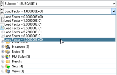
| 8. | Activate/Select the second window by clicking in it and load the displacement results similarly. However, since you have requested results for intermediate iterations via NLOUT, you will see results for all intermediate iterations. |
| 9. | In the Results browser, click Load Factor, and select the final increment Load Factor = 1.000000E+00. |
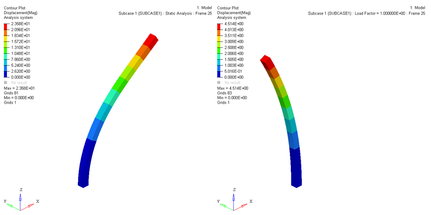
| 10. | The Displacement contour results are now displayed as shown below. You can clearly see that the activation of follower forces has modified the displacement profile significantly. |
Setting up the Rubber Disk model in HyperMesh
Step 8: Selecting the OptiStruct User Profile and loading the model into HyperMesh
| 1. | Similar to Step 1, select the disk_fllwer.fem file you saved to your working directory from the optistruct.zip file. |
The model is now loaded into HyperMesh.
Step 9: Creating Follower Load Bulk Data Entries for the three options
In the beam model in the first section of this exercise, follower loads for concentrated forces do not depend on the area of the element face to whose grids they are applied. Therefore, the results will remain the same for any activation option chosen on either the FLLWER bulk data entry or the PARAM,FLLWER entry. Additionally, since you only had one subcase, select the parameter PARAM,FLLWER to activate follower loading for this model.
In this current disk model, the loads are pressure loads which may depend on the area of the element faces to whom they are applied. Additionally, you have multiple subcases to showcase the effect of different FLLWER options. In the FLLWER bulk data entry in the OptiStruct help, you will see:
OPT
|
Options for the calculation of Follower Loads.
Default = 1 <-1, 0, 1, 2, or 3>
= -1, 0: Follower force calculation is not activated.
= 1: Follower effect is activated. For pressure load, both element surface area and load direction are updated during the solution. For concentrated force, only the force direction is updated.
= 2: Follower effect is activated. For pressure load, only element surface area is updated (load direction is not updated) during the solution. For concentrated force, only the force direction is involved; which is the same as OPT = 1.
= 3: Follower effect is activated. For pressure load, only load direction is updated (element surface area is not updated). For concentrated force, only the force direction is updated; which is the same as OPT = 1.
|
| 1. | Right-click in the Model browser, click Create and select Load Collector from the drop-down menu. |
| 2. | Name the load collector FLLWER_1. |
| 3. | In the corresponding Entity Editor, click on the field next to Card Image and select FLLWER. |
| 4. | Click on the field next to OPT and select 1 from the drop-down menu. |
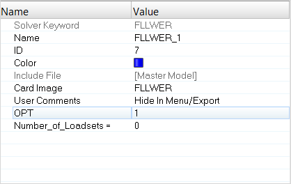
| 5. | Similarly, create load collectors FLLWER_2 and FLLWER_3 and select OPT=2 and OPT=3 respectively for each entry. |
Step 10: Referencing the FLLWER bulk entries in the Subcase section
The created FLLWER Bulk Data entries should now be selected in the Subcase section.
| 1. | Click on the fllwer_1 Load Step to open it in the Entity Editor. |
| 2. | Check the box next to FLLWER in the Subcase Options section of the Entity Editor. |
| 3. | Click on the field next to ID and then on the yellow Loadcol button. |
| 4. | Choose the FLLWER_1 load collector in the Select Loadcol dialog and click OK. |
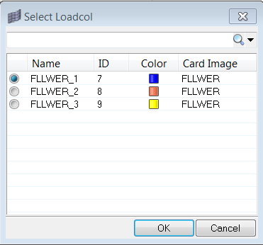
| 5. | Similarly, choose FLLWER_2 and FLLWER_3 load collectors for corresponding subcases fllwer_2 and fllwer_3 respectively. |
Step 11: Activating Nonlinear Intermediate Results (NLOUT)
Parameters that allow you to activate Nonlinear Intermediate Results are available via the NLOUT Bulk Data and Subcase entries. The number of intervals at which intermediate results are output is controlled by the NINT parameter. The SVNONCNV parameter can be used to activate/deactivate the output of results for non-convergent solutions. This is currently turned on by default (set to YES).
| 1. | Right-click in the Model browser, click Create and select Load Collector from the drop-down menu. |
| 2. | Name the load collector NLOUT. |
| 3. | In the corresponding Entity Editor, click on the field next to Card Image and select NLOUT. |
| 4. | Activate the check box next to NINT and in the VALUE field enter the integer 10 (which is the default). This indicates to OptiStruct that the maximum number of intervals at which intermediate results are requested is 10. If the load increment from any load “n” to load “n+1” is greater than 1/NINT (in this case, 1/10 is 0.1), then the results corresponding to load level “n+1” are saved for output; otherwise, the results are not saved. |
Note that this parameter has no control over the adaptive load size selection during the incremental-iterative solution process. It only specifies the number of intervals when results are saved for output during the solution process.
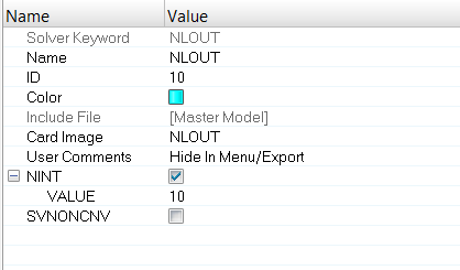
| 5. | Click on the fllwer_1 Load Step to open it in the Entity Editor. |
| 6. | Click on the field next to NLOUT and on the yellow Loadcol button. |
| 7. | Select the NLOUT load collector in the Select Loadcol dialog and click OK. |
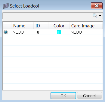
| 8. | Similarly, select the NLOUT load collector for fllwer_2, fllwer_3, and NO_fllwer subcases. |
Step 12: Running the Disk model with Follower Loads activation
The model now consists of loads which have been identified as follower loads. Additionally, you have learned how to request results at intermediate increments.
| 1. | Follow the instructions provided in Step 2 to save and launch OptiStruct. |
| 2. | For File name, enter disk_fllwer_ON.fem. |
If the job is successful, the new results files will appear in the directory from which disk_fllwer_ON.fem was selected. Look in the disk_fllwer_ON.out file for error messages that could help debug the input deck, if any errors are present.
Viewing and Post-processing the Results for the Disk Model
Displacements and Element Stresses are calculated by default and can be plotted using the Contour panel in HyperView.
Step 13: Comparing the Displacement Results between models with and without Follower Load activation
| 2. | Select the page window layout icon  to split the page into four windows. to split the page into four windows. |
| 3. | In the first window, load the disk_fllwer_ON.h3d file by clicking  and navigating to your working directory. and navigating to your working directory. |
| 4. | Select Subcase 1 (fllwer_1) and Load Factor = 1.000000E+00 in the Results browser. |
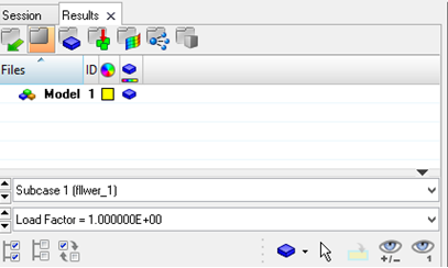
| 5. | Similarly load the disk_fllwer_ON.h3d file again in the second window and select Subcase 2 (fllwer_2). Repeat this process until the four windows contain results from four different subcases. |
| 6. | Activate/Select the first window by clicking in it and then click the Contour toolbar icon  . . |
| 7. | For Result type, select Displacement (v). |
| 9. | Activate/Select the second window by clicking in it and load the displacement results similarly. However, since you have requested results for intermediate iterations via NLOUT, you will see results for all intermediate iterations. This is the reason you navigate the final load factor to compare results. |
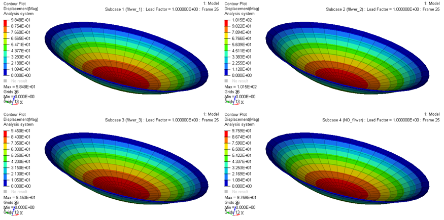
| 10. | The Displacement contour results are now displayed as in the figure below. You can clearly see that the activation of follower forces has modified the displacement profile significantly. Additionally, you can see that since subcase 3 (OPT=3) updates the load direction but not the area, the force (Pressure*Area) distribution at the grid points is low for Subcase 3 and the Displacement results reflect this when compared to OPT=1 and 2. |
See Also:
OptiStruct Tutorials


