
Pattern Repetition for Topography Optimization |

|

|

|

|
|
Pattern Repetition for Topography Optimization |
|
|
|

|
Pattern Repetition for Topography Optimization |
|
|
|
|
|
Pattern Repetition for Topography Optimization |
|
|
|
|
Pattern repetition is a technique where different structural components can be linked together so as to produce similar topographical layouts.
To achieve this goal, a master DTPG card needs to be defined, followed by any number of slave DTPG cards which reference the master. The master and slave components are related to each other through local coordinate systems, which are required, and through scaling factors, which are optional.
Other manufacturing constraints, such as pattern grouping, can be applied to the master DTPG card. These constraints will then automatically be applied to the slave DTPG card(s).
The following procedure should be followed to set up pattern repetition:
| 1. | Create a master DTPG card. |
| 2. | Apply other manufacturing constraints as needed. |
| 3. | Define the local coordinate system associated to the master DTPG card. |
| 4. | Create a slave DTPG card. |
| 5. | Define the local coordinate systems associated to the slave DTPG card. |
| 6. | Apply scaling factors as needed. |
| 7. | Repeat steps 4-6 for any number of slave DTPG cards. |
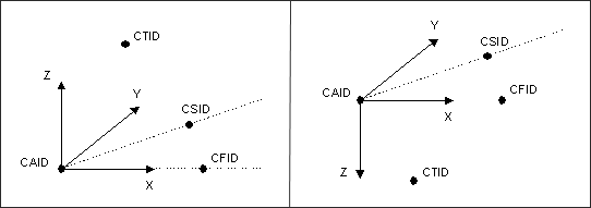
Local coordinates systems are generated by providing four points. These points can be defined either by entering explicit coordinates or by referencing existing grids, as follows:
| 1. | CAID defines the anchor point for the local coordinates system. |
| 2. | CFID defines the direction of the X-axis. |
| 3. | CSID defines the XY plane and indicates the positive sense of the Y-axis. |
| 4. | CTID indicates the positive sense of the Z-axis. |
The definition of the fourth point allows for both right-handed and left-handed coordinate systems, which facilitates the creation of reflected patterns.
Alternatively, local coordinate systems can be defined by referencing an existing rectangular coordinate system in the CID field, and by defining an anchor point in the CAID field.
Note that if the fields defining CFID, CSID, CTID, and CID are left blank, then the global coordinates system is used by default. The anchor point CAID, however, is always required.
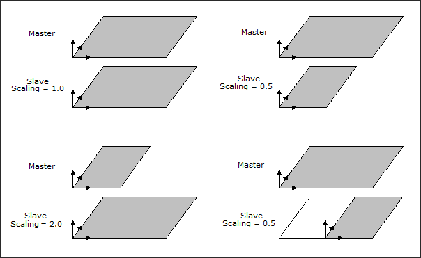
Scaling factors in the X, Y, and Z directions can be defined for each slave DTPG card. These factors are always related to the local coordinate system. By playing with the local coordinate systems and the scaling factors, a wide range of effects can be obtained as illustrated with the figure below.
See Also: