| 1. | Not all graphic types are supported by the Force_Contact modeling element. The graphic types that are supported are: |
The remaining graphic types are used for visualization only.
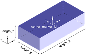
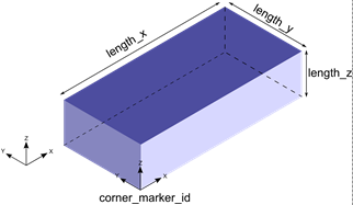
| 2. | The BoxDefinedFromCenter and BoxDefinedFromCorner graphic types are illustrated in the figure below. |
|
|
BoxDefinedFromCenter graphic type
|
BoxDefinedFromCorner graphic type
|
Both the BoxDefinedFromCenter and BoxDefinedFromCorner graphics are defined by their x, y, z lengths and a marker at the center or the corner, respectively.
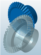
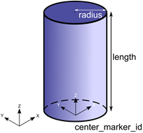
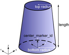
| 3. | The Cylinder and Frustum graphic types are illustrated in the figure below. |
|
|
Cylinder graphic type
|
Frustum graphic type
|
The Cylinder and Frustum graphics are defined by the radius (top and bottom in case of Frustum), length and the marker at the center of the geometry.
The TOP end of these graphics is the end that lies toward the negative Z axis, whereas the BOTTOM end is the one that lies toward the positive Z axis. These graphics may be defined with both, either TOP or BOTTOM, or neither ends capped. This is determined by the attribute ends_type:
| • | ends_type = “OPEN” implies that neither ends of the Cylinder or Frustum is closed |
| • | ends_type = “CLOSED” implies that both ends of the Cylinder or Frustum is closed |
| • | ends_type = “TOP_ONLY” implies that only the TOP end of the Cylinder or Frustum is open |
| • | ends_type = “BOTTOM_ONLY” implies that only the BOTTOM end of the Cylinder or Frustum is open |
Note: If you would like to use the Cylinder or Frustum graphic in your mesh based contact model, make sure that ends_type is set to CLOSED so that the Cylinder or Frustum graphic is closed. Closed geometry is a requirement for the mesh based contact in MotionSolve. For more details, see Best Practices for Modeling 3D Contact Models in MotionSolve in the MotionSolve User's Guide.
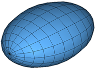
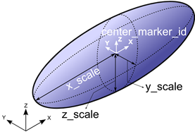
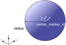
| 4. | The Ellipsoid and Sphere graphic types are illustrated in the figure below. |
|
|
Ellipsoid graphic type
|
Sphere graphic type
|
The Ellipsoid and Sphere graphic type are defined by the radii (x, y and z for Ellipsoid and a single radius for the Sphere) and the marker located at the center of the geometry.
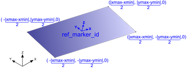
| 5. | The Plane and SPDP graphic types are illustrated in the figure below. |
|
|
Plane graphic type
|
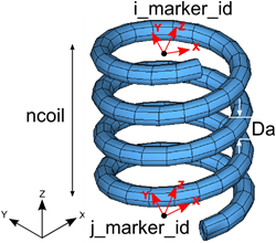
SPDP graphic type
|
The Plane graphic type is defined by the spatial extent (xmin, xmax, ymin, ymax) and a marker. This marker is positioned at the center of the plane, and the Z axis of this marker determines the normal to the plane. The spatial lengths are defined in the coordinate system of the ref_marker_id (shown in blue above).
The SPDP graphic type is defined by the two attachment markers for the I and J body, the number of coils in the spring and the diameter of the coil.
| 6. | The CircleFromRM and CircleFromRadius graphic types are illustrated in the figure below. |
|
|
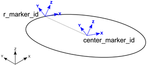
CircleFromRM graphic type
|
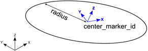
CircleFromRadius graphic type
|
The CircleFromRM graphic type is defined by two markers. The origin of the circle is centered at the origin of the marker specified by center_marker_id; also the Z axis of this marker determines the normal to the plane of the circle. The origin of the r_marker_id is used to determine the radius of the circle as  , where , where is the position of the center_marker_id and is the position of the center_marker_id and  is the position of the r_marker_id. is the position of the r_marker_id.
The CircleFromRadius graphic type is defined by a marker and the radius. The origin of the circle is centered at the origin of the marker specified by center_marker_id; also the Z axis of this marker determines the normal to the plane of the circle. The radius is specified by the radius attribute.
For visualizing both these graphics, the circle is drawn using a number of straight line segments connected together. The attribute nseg defines the number of segments that should be used to draw the circle. A larger value will result in a smoother looking graphic.
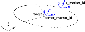
| 6. | The ArcFromRM and ArcFromRadius graphic are illustrated in the figure below. |
|
|
ArcFromRM graphic type
|
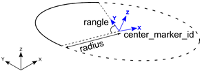
ArcFromRadius graphic type
|
The ArcFromRM graphic type is defined by two markers. The origin of the arc is set to the origin of the marker specified by center_marker_id; also the Z axis of this marker determines the normal to the plane of the circle. The origin of the r_marker_id is used to determine the radius of the circle as , where , where is the position of the center_marker_id and is the position of the center_marker_id and is the position of the r_marker_id. The arc is drawn starting from the Y axis of the center_marker_id, in a counter clockwise fashion for the included angle, specified by rangle. is the position of the r_marker_id. The arc is drawn starting from the Y axis of the center_marker_id, in a counter clockwise fashion for the included angle, specified by rangle.
The ArcFromRadius graphic type is defined by a marker and the radius. The origin of the arc is set to the origin of the marker specified by center_marker_id; also the Z axis of this marker determines the normal to the plane of the circle. The radius is specified by the radius attribute. The arc is drawn starting from the Y axis of the center_marker_id, in a counter clockwise fashion for the included angle, specified by rangle.
For visualizing both these graphics, the arc is drawn using a number of straight line segments connected together. The attribute nseg defines the number of segments that should be used to draw the arc. A larger value will result in a smoother looking graphic.
| 7. | The LineFromMesh and Point graphic types are illustrated in the figure below. |
|
|
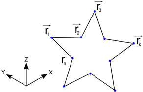
LineMesh graphic type
|
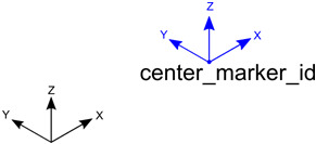
Point graphic type
|
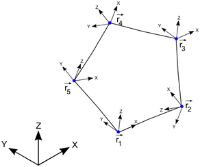
The LineFromMesh graphic type connects a number of vertices with straight lines. The number of lines to be drawn is specified by the num_line attribute. The X, Y and Z positions of the vertices are specified in the order in which the lines are to be drawn. For the above example, the vertices are specified in the following order:
The order above specifies a line to be drawn between r1 and r2, r2 and r3, and so on.
The Point graphic type is defined as the point that is specified by the origin of the center_marker_id.
| 8. | The LineFromMesh and Point graphic types are illustrated in the figure below. |
|
|
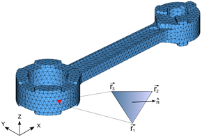
TriaMesh graphic type
|
Outline graphic type
|
The TriaMesh graphic is defined as a collection of triangle elements that usually share vertices and edges between them. This type of mesh is commonly used for representing CAD geometry in analysis. The triangles, by themselves are 2D. When connected together, these triangles can represent a 3D surface. The surface may or may not have free edges. Further, there is no requirement that the mesh defines a contiguous solid. In other words, all parts of the mesh need not be connected.
The surface normal at each triangle is defined as the cross product of the edges such that the normal points outward when the vertices are specified in a counter-clockwise manner. In the figure above, the normal is defined as  . .
The Outline graphic is defined by a list of marker IDs. A poly line is drawn through the origins of each of these markers. The number of markers is specified by the attribute num_marker_id.
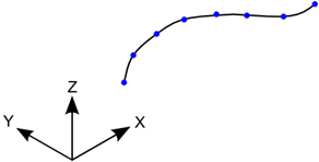
| 10. | The ParamCurve and DeformCurve graphic types are illustrated in the figure below. |
|
|
ParamCurve graphic type
|
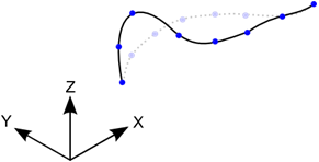
DeformCurve graphic type
|
The ParamCurve graphic type is used to represent a curve defined in the model as a Reference_ParamCurve element. The graphic is defined by a number of straight line segments connecting vertices on the curve defined by curve_id.
The DeformCurve graphic type is used to represent a deformable curve defined in the model as a Reference_DeformCurve element. The graphic is defined by a number of straight line segments connecting vertices on the curve defined by curve_id. Since this graphic represents a deformable curve, the graphic deforms along with the curve as the simulation progresses.
The attribute nseg defines the number of segments that should be used to draw the curves. A larger value will result in a smoother looking curve. Depending on how the points are defined, the ParamCurve or DeformCurve graphic can be open or closed.
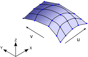
| 11. | The ParamSurface and DeformSurface graphic types are illustrated in the figure below. |
|
|
ParamSurface graphic type
|
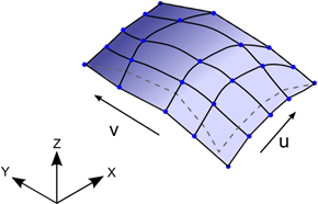
DeformSurface graphic type
|
The ParamSurface graphic type is used to represent a surface defined in the model as a Reference_ParamSurface element. The graphic is defined by a number of straight line segments connecting vertices on the surface defined by surface_id.
The DeformSurface graphic type is used to represent a deformable surface defined in the model as a Reference_DeformSurface element. The graphic is defined by a number of straight line segments connecting vertices on the surface defined by surface_id. Since this graphic represents a deformable surface, the graphic deforms along with the surface as the simulation progresses.
The attribute nseg_u and nseg_v defines the number of segments that should be used to draw the curves along the U and V directions of the surface respectively. Larger values will result in a smoother looking surface.
| 12. | The Parasolid graphic type allows you to use Parasolid geometry as a graphic in MotionSolve. The graphic is defined by the name and location of the Parasolid graphic file and the name(s) of the parts in the Parasolid assembly. |
Specifying your geometry as a Parasolid graphic offers an advantage when using the graphic for contact simulations. Since there is no discretization of the surface into triangles, the surface of the Parasolid graphic is smoother than its meshed counterpart, resulting in smoother contact forces.
To import Parasolid geometry into your model, you must use Import CAD or FE from the Tools menu in MotionView. Please see tutorial MV-1035 for more information.
After the simulation is complete, MotionSolve tessellates the Parasolid geometry and writes it to the animation H3D file for visualization.
| 13. | The UserGra graphic type allows you to define your own graphic. This can be done by defining your own subroutine or script. You can create vertices and triangles using the access functions ADD_GRA_NODE, SET_GRA_NODE and ADD_GRA_TRIA provided by MotionSolve. These access functions allow you to create a triangular mesh that can be then used as a graphic in your model. For more information and examples, please refer to the documentation on GRASUB. |
Using a GRASUB is particularly useful when you would like to redraw your graphic as the simulation progresses.
| 14. | If you want to use CAD geometry (other than Parasolid geometry, for example IGES, STP etc.) for contact modeling, then the native CAD format needs to be converted to Triamesh elements. This can be done in two ways: |
| • | Import the CAD model into HyperMesh, mesh it, and export the H3D file. Import this H3D file into MotionView and define contact. |
| • | From within MotionView, select Import CAD or FE from the Tools menu in MotionView. This utility uses HyperMesh to perform the translation. It is intended for those who are not familiar with HyperMesh. |
| 15. | All graphic entities are written to the animation H3D file so the system behavior can be visualized in HyperView. |
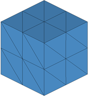
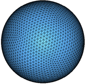
| 16. | All primitive 3D graphics (Sphere, Ellipsoid, Cylinder, Frustum, BoxDefinedFromCorner and BoxDefinedFromCenter) are converted to a triangular meshed representation when they are used for contact simulations and also when they are written to the animation H3D file. |
The density of their mesh can be controlled by the parameter refinement_level. A higher value of refinement_level increases the mesh density by adding more and more triangles.
A higher mesh density tends to produce more accurate contact forces, however adding more triangles usually increases the simulation time.
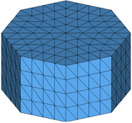
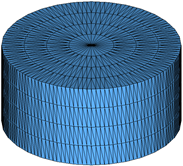
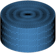
The following figures show the effect of increasing refinement level on some of the primitive 3D shapes.

|
|
|
Box with refinement_level = 0
|
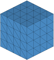
Box with refinement_level = 1
|
Box with refinement_level = 2
|
|
|
|
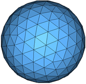
Sphere with refinement_level = 2
|
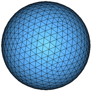
Sphere with refinement_level = 3
|
Sphere with refinement_level = 4
|
|
|
|
Cylinder with refinement_level = 1
|
Cylinder with refinement_level = 2
|
Cylinder with refinement_level = 3
|
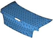
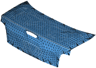
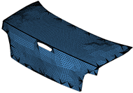
The refinement_level attribute may also be used for a TriaMesh graphic type. Increasing the refinement level by 1 results in each triangle being divided into 4 triangles as illustrated in the figures below. Note: if you wish to use your TriaMesh graphic as is, set this attribute to 0 or do not define it.
|
|
|
Triamesh with refinement_level = 0
|
Triamesh with refinement_level = 1
|
Triamesh with refinement_level = 2
|
The refinement_level is supported for the following graphic types:
|