|
»Click here to display Table of Contents«
|

Interfaces |

|

|

|

|
|
Interfaces |
|
|
|

|
|
»Click here to display Table of Contents«
|
Interfaces |
|
|
|
|
|
Interfaces |
|
|
|
|
Available contact algorithms in RADIOSS are presented in the following table.
Type |
Description |
Application |
Contact Treatment |
|---|---|---|---|
1 & 9 |
ALE / LAG with sliding |
Fluid-structure interaction |
Master-Slave |
2 |
Tied interface |
Change of mesh density (solid) |
Master-Slave or LM |
3 & 5 |
Contact impact between two parts |
Use of type 7 is recommended |
Penalty |
6 |
Contact impact between two rigid bodies |
User-defined contacts |
Penalty |
7 |
General purpose contact impact between two parts |
Solid contact impact at all speeds |
Penalty or LM |
8 |
Drawbead contact |
Stamping applications |
Penalty |
10 |
Similar to type 7, but tied contact |
Special purpose interface |
Penalty |
11 |
Impact between two lines |
For beams, bars or springs |
Penalty |
12 |
Fluid / fluid contact |
Fluid to fluid contact |
Penalty |
16 & 17 |
Contact between nodes to quadratic shape solids and solid-shells or between quadratic shapes |
Meshes with 8-node or 16-node thick-shell or 20 bricks |
LM |
18 |
CEL Lagrange / Euler interface |
Fluid-structure interactions |
Penalty |
RADIOSS Interfaces part-to-part
The specific interfaces for RADIOSS ALE/CFD applications are:
| • | Type 1: to contact an ALE part to a Lagrangian part |
| • | Type 2: for ALE/Euler bricks to contact moving or fix meshes |
| • | Type 18: to treat fluid-structure interactions |
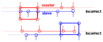
Interface type 12 is designed to connect two non-conforming meshes. Its use is restricted to a master/slave approach, that is, no more than one master node is connected to a slave segment.
Note that the master/slave search algorithm may fail where there are sharp angles. In this case, you must split the interface into several interfaces.
One might also detect an error when the closest master node of a given slave node does not belong to the segment in front a slave node. In this case, adjust the mesh locally to avoid ambiguous situations.
The interface is available for quasi-compressibility and compressibility options.
Every slave node needs a master segment.
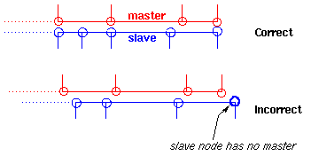
This must remain true when interface is moving.
If a node has no projection on the master surface, the algorithm issues a warning but still works, because the slave node remains associated to the nearest master segment.
Every master node must receive contribution from at least a slave node.
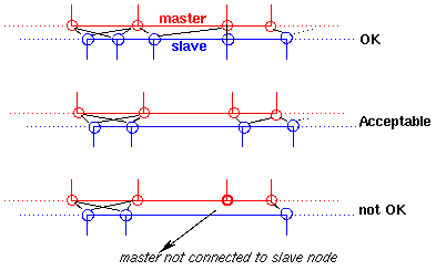
If a master segment does not have a slave but its neighbors do, the algorithm still works, because the above rule is satisfied. In principle, it is nevertheless recommended that master segments have at least one slave node.
One can say that the slave grid must be finer or equal to the master.
When compressible, any segment (master or slave) must be a surface of one and only one ALE brick element.
Kinematic conditions on the slave side are allowed only if consistent with an identical condition on the master side.
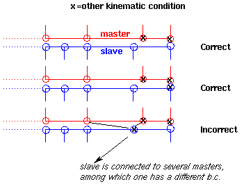
This has to remain true when interface slides.
Three kinds of interfaces are available:
Interface type 1 is used to define boundaries between ALE and Lagrange domains. Full slip conditions are applied at the boundary between the two domains. Normal material velocities of Lagrange and ALE nodes are equally set.
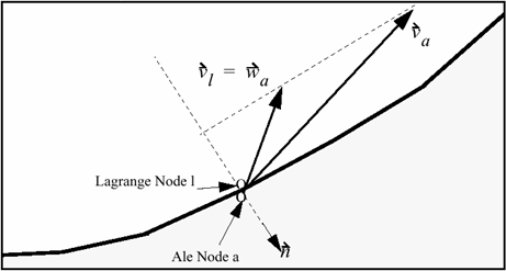
Fluid-Structure Interaction with interface type 1
This is an ALE/Lagrange interface with void opening and free surface (that is: if the master and slave sides are not in contact, there is no interaction between them). An ALE part is defined as slave and the Lagrangian part is defined as master. The grid velocity is equal to the material velocity in normal direction.
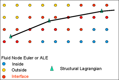
Interface type 18 creates contact between Euler/ALE nodes and a Lagrangian master surface. Visco-elastic penalty method is used to impose a relative material (fluid) velocity tangent to the master surface. The grid velocity is not modified by this interface. The interface allows the simulation of the penetration of a Lagrangian part (structure) into an Euler/ALE mesh, for example in the case of ship slamming.
The quality of simulation results using this interface depends strongly on the interface parameters and especially on the stiffness of the interface.
A recommended stiffness factor of the interface for fluid structure interaction problems can be obtained by:
Where, ![]() is the (highest) fluid density, V is the velocity of the phenomenon (speed of the sound or higher for supersonic phenomenon), and Sel is the surface of the Lagrangian elements.
is the (highest) fluid density, V is the velocity of the phenomenon (speed of the sound or higher for supersonic phenomenon), and Sel is the surface of the Lagrangian elements.
For aerodynamic problems, the recommendations are:
| • | gap = 1.5 Lc with Lc being the length of fluid element |
| • | Constant stiffness with K = gPLc |
| • | Viscosity related to the interface stiffness: |
![]()
With ![]() = 0.5 or
= 0.5 or ![]() =
= ![]()
P and ![]() are the air characteristics
are the air characteristics
Fluid-Structure Interaction with interface type 18
The recommended gap value is equal to 1.5 by the element size. Note that the interface needs a fine enough mesh to provide appropriate results.