Two kinds of kinematic conditions are available:
| • | Conditions applied on the material velocities |
| • | Conditions on grid velocity (ALE) |
By default, all kinematic conditions are applied to the material, not to the grid. For ALE applications, options of interest are:
| • | fixed and full slip boundary conditions |
| • | imposed velocities (for example: imposed flux at inlet) |
| • | rigid links (temporary adds during restarts) |
| • | rigid bodies to model rigid structures and connections and also to compute drag and lift forces (that is, fluid impulse on rigid body is stored in time history database). |
Boundary Conditions
ALE boundary conditions are activated by using /ALE/BCS keyword in the input deck. Grid constraints act only on grid velocities. If a boundary condition is not specified for grid velocity, nodes may move in any arbitrary manner (ALE). An example of an ALE boundary condition is shown in the following figure.
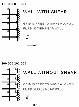
Example of ALE boundary condition applications
Rigid Body (/RBODY)
A rigid body is defined by a master node M and a set of slave nodes. Rigid bodies are used in CFD application to compute reactive forces on structures.
ALE link is a set of n nodes with grid velocity controlled by two master nodes M1 and M2. Input data is done at each restart (temporary add). Three options are available:
| • | Velocity is linearly interpolated with respect to input order |
| • | Velocity is set to maximum absolute velocity of master nodes |
| • | Velocity is set to minimum absolute velocity of master nodes |


