Introduction
This tutorial presents the different steps involved in building a simple Sled model using HyperCrash pre-processing tool.
Exercise
Step 1: Model Import
Set the User Profile, units and interface.
| 2. | For User Profile, select RADIOSS V14. |
| 3. | For Unit System, select N_mm_s_T. |
| 4. | For User Interface Style, select New. |
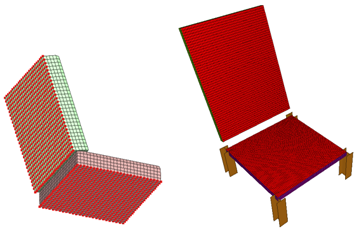
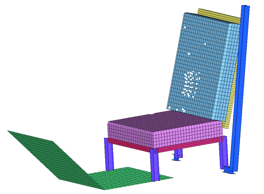
Step 2: Import the seat model and merge all components, floor, seatbelt and foam block
| 1. | Click File > Import > RADIOSS. |
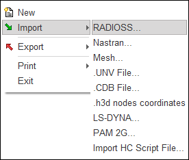
| 2. | Select the file SEAT__00D00.rad. |
Step 3: Model Merging
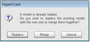
| 1. | Click File > Import > RADIOSS. HyperCrash message window prompt. |
| 3. | Select the file FLOORD00.rad. |
| 5. | In the Set all to field, enter the value 100000. |
| 6. | Click the Set all to button to offset the numbering of all the entities. |
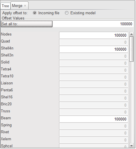
| 7. | Click Merge to merge the floor model. |
| 8. | Redo the steps 1 to 7 for the cushion model: |
| • | Set all to offset: 200000 |
| 9. | Redo the steps 1 to 7 for the seatbelt model: |
| • | Set all to offset: 300000 |
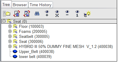
Step 4: Model Hierarchy
| 1. | In the Tree, select the subset of the seat named Seat model (300005). |
| 2. | Right-click and select Change Name. |
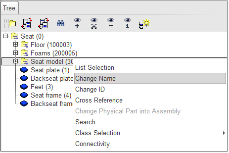
| 3. | In the Change Name window, enter the name Seatbelt. |
| 5. | Click any item on the tree, right-click and select New Assembly. |
| 6. | Enter the name Frame and click Ok. |
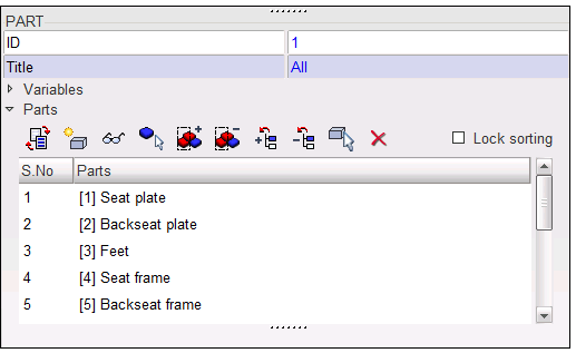
| 7. | Select the parts Seat plate, Backseat plate, Feet, Seat frame, and Backseat frame using the SHIFT or CTRL keys. |
| 8. | Press and hold the middle mouse button and drag the selected parts into the new assembly Frame. |
| 9. | Select the Tree root (Seat) and right-click. |
| 10. | In the pop-up menu, select List Selection. The List Selection dialog opens. |
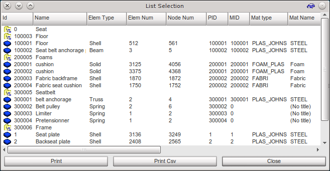
| 11. | In the displayed window, check if all parts have properties (PID) and materials (MID). |
| 12. | Click Close and Export the model to save. |
Step 5: Connection
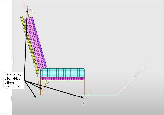
To add the feet of the seat and the seatbelt anchorage point to the floor rigid body.
| 1. | Click Mesh Editing > Rigid Body. |
| 2. | Select the rigid body: Floor. |
| 3. | Click See selected rigid bodies ( ). ). |
| 4. | Click Display All  and then Left View (F11). and then Left View (F11). |
| 5. | Right-click in the Grnod_Id entry box and click Select in graphic, click  Add nodes by box selection and select all the nodes of the seat, feet and the anchorage points of the seatbelt. Add nodes by box selection and select all the nodes of the seat, feet and the anchorage points of the seatbelt. |
| 6. | Right-click to validate. |
| 7. | Select the Floor rigid body in the list, right-click and add the rigid body and master node to time history. |
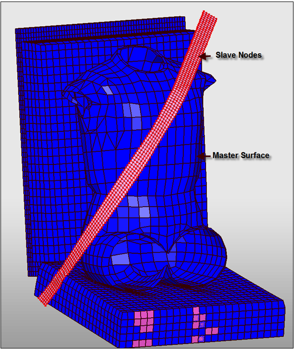
Connect Seat Cushion to the seat frame with a tied interface (Type 2)
| 1. | Click LoadCase > Contact Interface. |
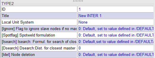
| 2. | Right-click in the window and select Create New > Kinematic condition (Type 2). |
| 3. | Display only the cushion parts. Press F11 for XZ view, select Slave nodes section, and click Add noes by box selection. |
| 4. | Holding down the SHIFT key, click to draw a polygon window around nodes on the backside of cushion of the nodes. |
| Tip: | Press the letter P for non-perspective view, if needed.
Press SHIFT and draw a closed polygon window around the nodes to select. When finished, release the SHIFT key. |
|
| 5. | Display Frame Assembly in the Tree, pick Master surface section, click Add/Remove a face and pick one element on each part of the frame facing the cushion. Then select the Expand option on the lower right corner to pick select all. Add/Remove a face and pick one element on each part of the frame facing the cushion. Then select the Expand option on the lower right corner to pick select all. |
| 6. | Select the Expand option on the lower right corner to select all the elements of the seat assembly facing the seat cushions. |
| 7. | Click Yes or Enter on the keyboard to end the selection. |
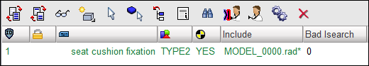
| 8. | For the Title of the contact, enter seat cushion fixation. |
| 10. | Click  at the top of the interface panel, to check the interface. The created interface should be displayed with green text, as shown below. Otherwise, the interface has to be modified. at the top of the interface panel, to check the interface. The created interface should be displayed with green text, as shown below. Otherwise, the interface has to be modified. |
| 12. | Export the model to save. |
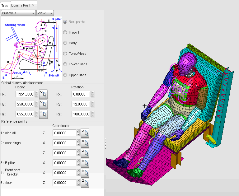
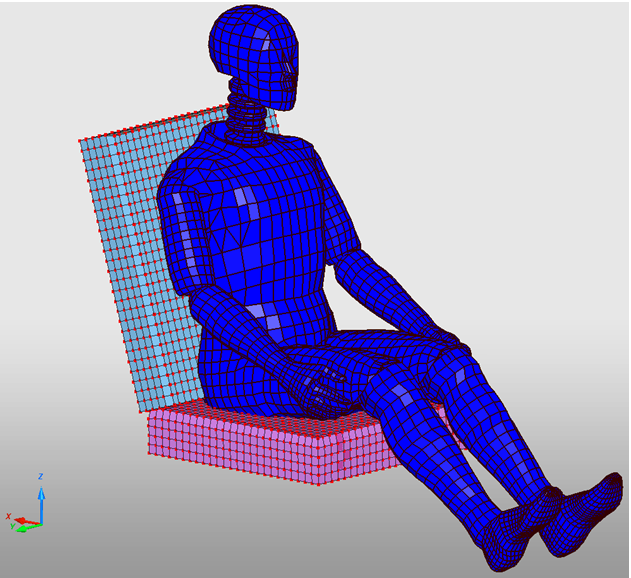
Step 6: Dummy positioning
| 1. | Click Safety > Dummy Positioner. |
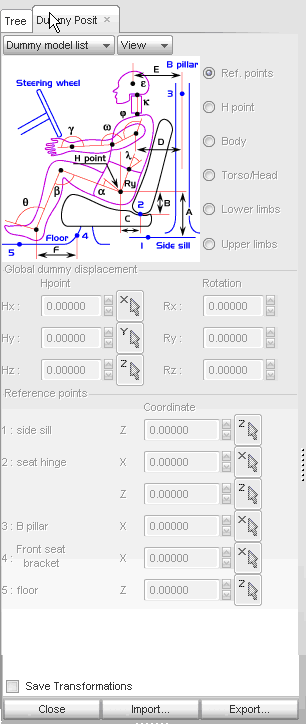
| 2. | From the Dummy model list menu, select New dummy. |
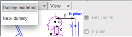
A DummyMng panel opens.
| 3. | Select the File subpanel. |
| 4. | Select the file H350R12BD00. The dummy model is displayed in the small graphic window. |
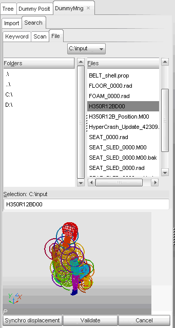
| 6. | Set Set all to value to 400000. |
| 7. | Click the Set all to button to offset the numbering of all entities. |
| 8. | Click OK to merge the Dummy model. |
| 9. | Click Import in the dummy positioning window and select the file H350R12B_Position.M00 and click OK. |
| Note: | H350R12B_Position.M00 contains all parameters for the automatic dummy positioning. |
|
| 10. | Close the Dummy positioner and Export the model to save. |
Step 7: Seatbelt setting
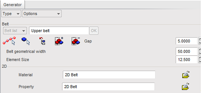
| 1. | Click Safety > Belt Generator. |
| 2. | Enter the name Upper belt and click OK to validate. |
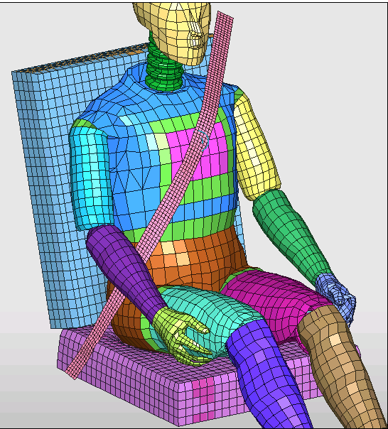
| 3. | Click Seat belt reference points ( ). ). |
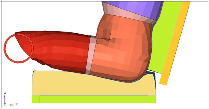
| 4. | Click Add nodes by picking ( ) and select three nodes, as shown in the following image (red dots). ) and select three nodes, as shown in the following image (red dots). |
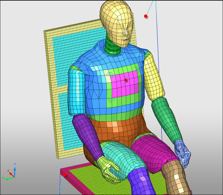
| 5. | Click Yes on the right corner and OK to validate the node selection. |
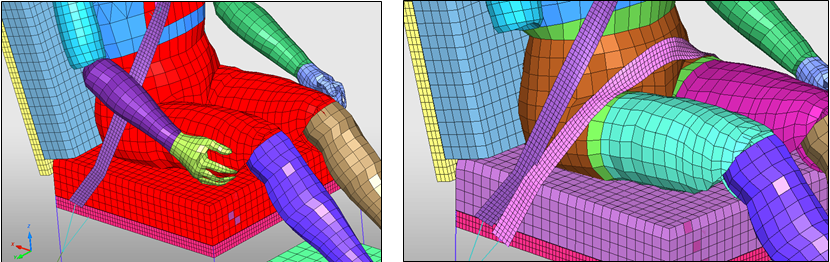
| 6. | Click Add/Remove body parts ( ) and select the parts: torso, pelvis, upper legs, and the seat cushion fabric, as shown in red in the image. ) and select the parts: torso, pelvis, upper legs, and the seat cushion fabric, as shown in red in the image. |

| 7. | Click Yes to validate the selection. |
| 8. | Set the Gap value to 5.00 mm. |
| 9. | Set the Belt geometric width to 40. |
| 10. | Set the Element Size to 8. |
| 11. | Click Material (  ) and select the material file BELT.mat you saved to your working directory from the radioss.zip file. Refer to Accessing the Model Files. ) and select the material file BELT.mat you saved to your working directory from the radioss.zip file. Refer to Accessing the Model Files. |
| 13. | Click Property ( ) and select the property file BELT.prop you saved to your working directory from the radioss.zip file. |
| 15. | Click the Preview button to display the proposed seat belt. Some intersections may exist between the seat cushion and the seat belt. |
| 16. | Use the orientation tools to modify the angle of the Rigid Body 2. |
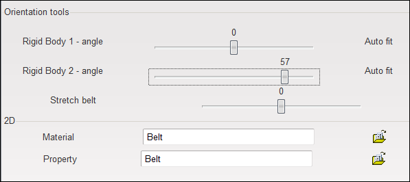
| 17. | Click Save to save the belt definition. |
| 18. | Redo the same operations in order to create the lower belt. Select nodes, as shown below: |
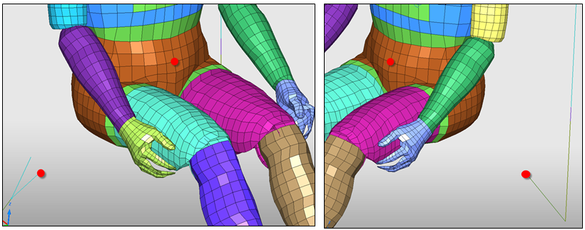
| 19. | Select the parts: pelvis, upper legs and seat cushion fabric. |
| 20. | Click Preview > Save > Close. |
| 21. | Export the model to save. |
Seatbelt vs Dummy
Step 8: Contact interfaces
During the seatbelt creation, two contact interfaces between the seatbelt and the dummy have been created. You will need to check and remove any remaining intersections and penetrations.
| 1. | Click LoadCase > Contact Interface. |
| 2. | Select interface BELT ID 400038. |
| 3. | Click See selected () to display. |
| 4. | Click in Master Surface, right-click in the graphic area, and click Include picked parts, to select the Fabric backframe and the Backseat frame as they may come into contact with the shoulder belt during the analysis. |
| 6. | Select interfaces BELT ID 400038 and BELT ID 400039. |
| 7. | Click See selected () to display. |
| 8. | Set Coulomb friction to 0.3. |
| 9. | Set Friction penalty formulation to 2. |
| 11. | Select interfaces BELT ID 400038 and BELT ID 400039. |
| 12. | Click Check penetration selected interfaces ( ). ). |
| 13. | In the Quality panel remove the intersections and penetrations, using the Depenetrate Auto ( ). ). |
| 14. | Click Close in order to come back to the Contact Interface panel. |
| 15. | Export the model to save. |
Seat structure
Creation of Self-Impact between different parts of the Seat.
| 1. | In the Tree window, select subsets Frame, Floor and Foam. Click the Isolate icon  . . |
| 2. | Right-click in the Contact list and select Create New > Multi-usage (Type 7). |
| 4. | Set the Title to Self impact seat structure. |
| 5. | Set Gap/element option to Variable gap. |
| 6. | Set Coulomb friction to 0.2. |
| 7. | Set Friction penalty formulation to 2. |
| 8. | Right-click in the Master Surface entry box and click Select in graphics > Add selected parts of tree ( ). ). |
| 10. | Select the self impact seat structure interface in the list. |
| 11. | Click Check penetration selected interfaces ( ). Some penetrations exist between the seat cushion and the seat structure. |
| 12. | Switch to the Tree window, and select the subset named Frame. |
| 13. | Switch to the Quality window and click Fixed part ( ). |
| 14. | Press the ESC key to remove all selected parts. |
| 15. | Click Add selected parts of tree ( ). |
| 16. | Click Depenetrate Auto ( ). |
| Note: | Only the nodes of the seat cushion are moved. The seat parts are fixed. |
|
| 18. | Export the model to save. |
Dummy vs Seat
Creation of Interface between Dummy and Seat.
| 1. | Click LoadCase > Contact Interface. |
| 2. | Select interface Create/Modify > Multi usage (Type 7). |
| 3. | In the Tree window, select the Foams subset - the two cushion parts only. |
| 4. | Switch back to the Interface panel and right-click in the Slave Nodes entry box and click Select in graphics > Add selected parts of Tree (). |
| 5. | Again switch to the Tree window. |
| 6. | Select the subset named HYBRID III 50% DUMMY FINE MESH V_1.2. |
| 7. | Switch back to the Contact interface panel and right-click in the Master Nodes entry box and click Select in graphics > Add selected parts of Tree (). |
| 8. | Set the interface Title to Dummy - Seat. |
| 9. | Set Coulomb friction to 0.3. |
| 10. | Set GAP MIN to 3.00mm. |
| 11. | Set Friction penalty formulation to 2. |
| 13. | Export the model to save. |
Dummy vs Floor
Creation of an interface between dummy feet and the floor.
| 1. | Right-click in the Contact list and select Create New > Tied with void (Type 10). |
| 2. | Set the dummy feet as slave nodes. |
| 3. | Set the floor as master surface. |
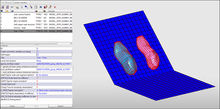
| 4. | Set the interface Title to Feet – Floor. |
| 5. | Set Gap for impact activation to 3.0 mm. |
| 7. | Export the model to save. |
Seat Deformer
Modifying the seat cushion mesh to conform to the dummy using the Seat Deformer tool.
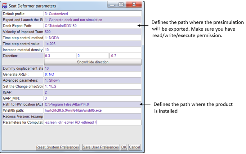
Step 1: Edit Pre-simulation settings
To remove the intersection between the dummy and the set HyperCrash will generate a RADIOSS input deck and run a pre-simulation step. The settings for the pre-simulation are defined in the menu Option > Presimulation Parameters (for Seat Deformer). For this exercise, modify the settings, as shown below:
Step 2: Select Seat Parts
| 1. | In the Tree browser, select Foams assembly, Seat plate, Backseat plate, Seat frame, and Backseat frame, as shown below. |
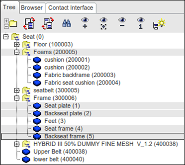
| 2. | Click Safety > Seat Deformer > Pre-simulation (new) and click Add selected parts of Tree (). |
Step 3: Select Fixed Nodes
| 1. | In the Tree browser, select the Seat plate, Backseat plate, Seat frame and Backseat frame, as shown below. |
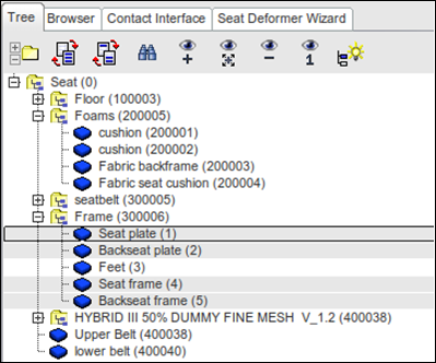
| 2. | Switch back to the Seat Deformer Wizard and click Add selected parts of Tree (). |
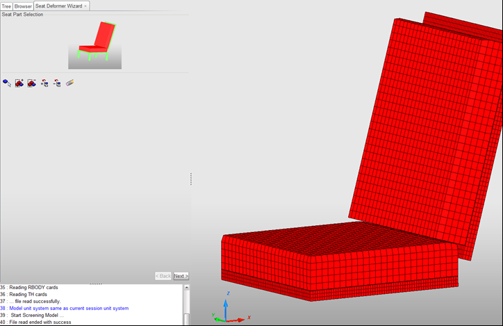
Step 4: Select Dummy Parts
| 1. | Select the dummy parts, as shown below. |

| 2. | Click Run and the pre-simulation will start. |
Step 5: Review the results and apply the deformed shaped
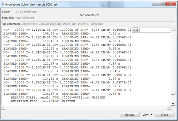
| 1. | Once the pre-simulation is completed review the results in HyperView by opening the h3d file. Create a cut section in the middle of the dummy and verify that the dummy does not intersect/penetrate the seat foam. |
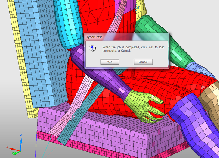
| 2. | If an intersection/penetration does not exist, go back to the HyperCrash window and load the results by clicking Yes in the dialog. |
| 3. | When the job is completed, click Yes to load the results. |
You can also load the results by clicking File > Import > .h3d node coordinates, then click Yes to the "Warning: all the nodes coordinates will be replaced by the ones found in the selected .h3d file."
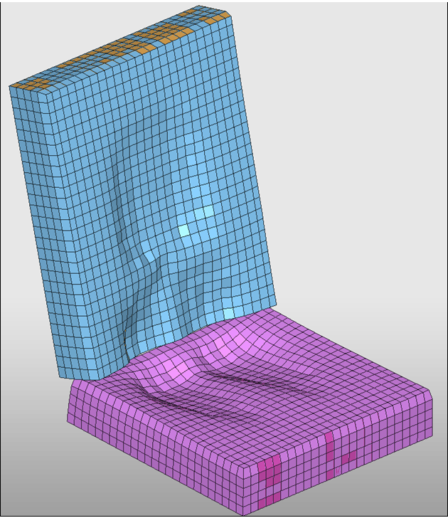
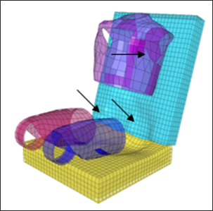
| 3. | Below is the deformed shape for the seat foam after the pre-simulation. |
After the seat deformation, check if any initial penetrations remain between the seat and the dummy.
| 1. | Click LoadCase > Contact Interface to open the Contact Interface tab. |
| 2. | Select interface Dummy – Seat. |
| 3. | Click Check penetration selected interfaces ( ). Penetrations exist between the seat beam and the dummy. |
| 4. | Click Select All (  ). ). |
| 5. | Click Highlight by Vector ( ). ). |
| 6. | Click Fixed part () . |
| 7. | Press the ESC key to remove all selected parts. |
| 8. | Click Fixed part () and then select the displayed parts of the dummy. |
| 9. | Click Depenetrate Auto (). Only the nodes of the seat cushion are moved. The parts of the dummy are fixed. |
| 10. | Click Close and then Export the model to save. |
Loadcase Setting
Step 9.1: Initial velocity
Update the initial velocity defined in the model to include all the nodes in the model.
| 1. | Click LoadCase > Initial Velocity to open the Initial Velocity tab. |
| 2. | Select the initial velocity All in the list. |
| 3. | Click See selected initial velocity (). |
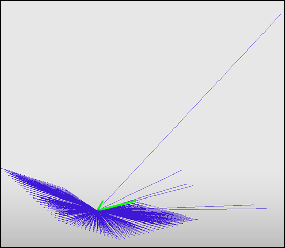
| 4. | Right-click in the Support entry box and click Select in graphics > Add all nodes ( ). ). |
| 5. | Change [Vx] X Velocity from –10000 to –13000 mm/s. |
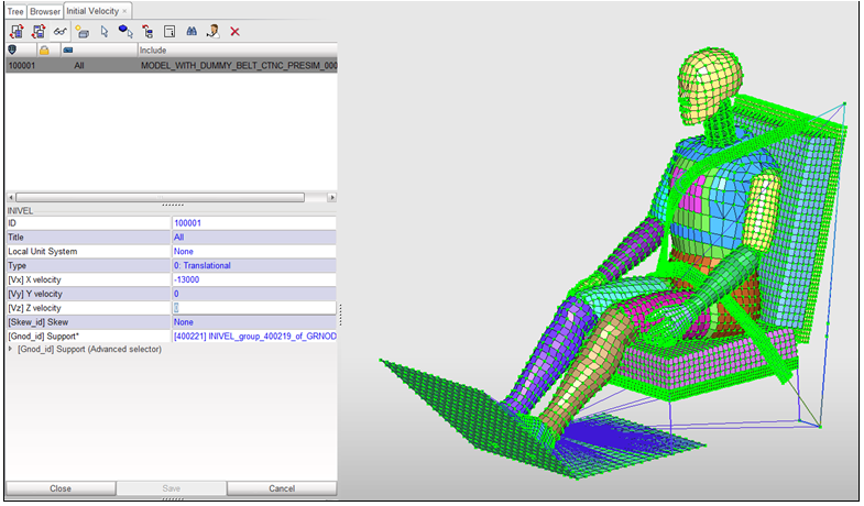
| 7. | Export the model to save. |
Step 9.2: Imposed velocity
Update the imposed velocity on the floor to decelerate the car.
| 1. | Click LoadCase > Imposed > Imposed Velocity. |
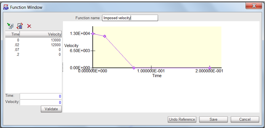
| 2. | Select Imposed velocity in the list. |
| 3. | Click See selected imposed velocity (). The floor rigid body is displayed on the screen. The imposed velocity is defined on its master node. |
| 4. | Right-click the Time Function entry box and select Edit function. Check if the initial value of the function is the same as the initial velocity. |
| 6. | Export the model to save. |
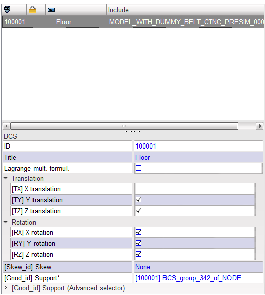
Step 9.3: Boundary conditions
To simulate the Sled Test, you need to constrain all degrees of freedom on the floor except X-direction.
| 1. | Click LoadCase > Boundary Condition. |
| 2. | Select Floor in the list. |
| 3. | Click See selected boundary condition (). The floor rigid body is displayed on the screen. The boundary condition is defined on its master node. |
| 4. | Verify that the degree of freedom for Ty, Tz, Rx, Ry, and Rz are fixed. |
| 6. | Export the model to save. |
Time History Data Setting
Step 10.1: Nodes
| 1. | Click Data History > Time History. |
| 2. | Select the node group H350MEF2D00_th_nodes. |
| 3. | Click See selected th (). These are the nodes of the dummy rigid bodies. |
| 4. | For the first 5 nodes of the group: |
| • | Select the node in the list. |
| • | Click See selected node (). |
| • | Enter a name in the field Node name, as shown in the table. |
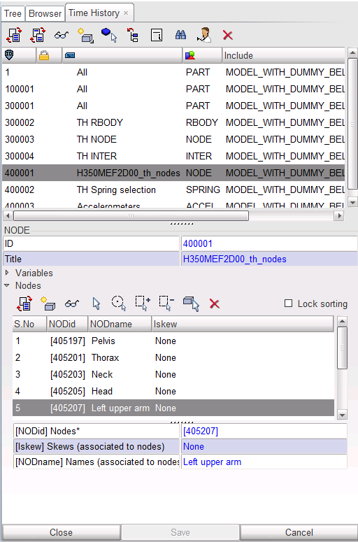
| 5. | When all labels are defined, click Save > Close. |
| 6. | Export the model to save. |
Step 10.2: Parts
| 1. | Click Data History > Time History. |
| 2. | Select the second and third part group on the list. |
| 3. | Click Delete selected th ( ). ). |
| 4. | Click Yes to the question in the main window (Yes or Cancel). The selected parts groups are deleted from the model. |
| 5. | Select the remaining part group in the list. |
| 6. | Click See selected th (). |
| 7. | Go to the Tree panel and select the root of the tree. |
| 8. | Switch back to the Data History panel and click Add parts by tree selection ( ). ). |
| 9. | Click Save and then Export the model to save. |
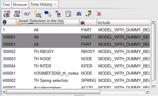
Step 10.3: Interfaces
To add all interfaces to Time History.
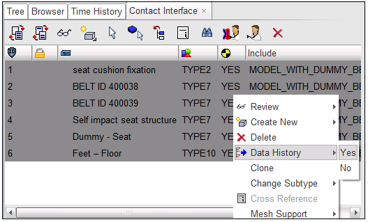
| 1. | Click LoadCase > Contact Interface to open the Contact Interface tab. |
| 2. | Select all interfaces in the list. |
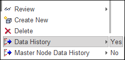
| 3. | Right-click and select Data History > Yes. |
Step 10.4: Final Check
| 2. | Select Check All Solver Contact Interfaces. |
| 3. | Make sure there are no intersections and initial penetrations; if so, fix them. |
| 5. | Go to Mesh Editing and clean so all the unused materials and properties are removed. |
Step 11: Create Control Cards and Export the Model
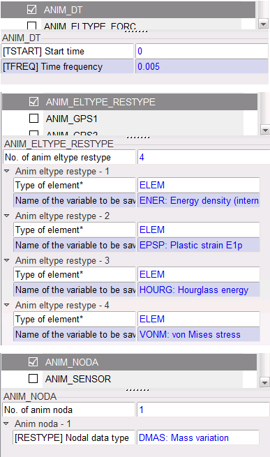
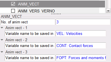
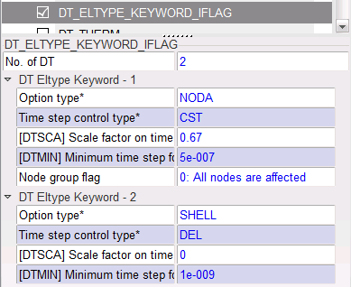
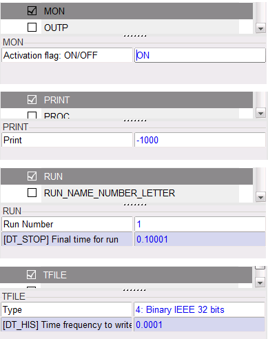
| 1. | Click Model > Control Cards to create the Control Cards in the images below. |
Note that the /DT/SHELL/DEL command is used to delete some of the rigid body shells to allow the dummy’s joints to bend during the simulation.
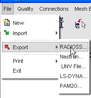
| 2. | Click File > Export > RADIOSS. |
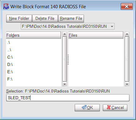
| 3. | Enter a name for the model in the file output window and click OK. |
| 4. | Write relevant information regarding your model in the Header window. |
The model is now ready to be computed.
See Also:
RADIOSS Tutorials
HyperCrash User's Guide


