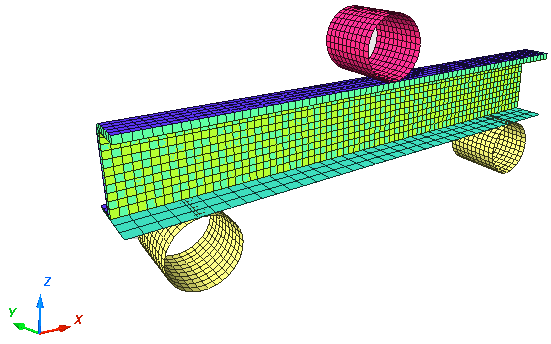
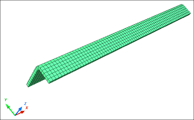
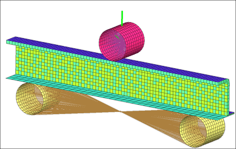
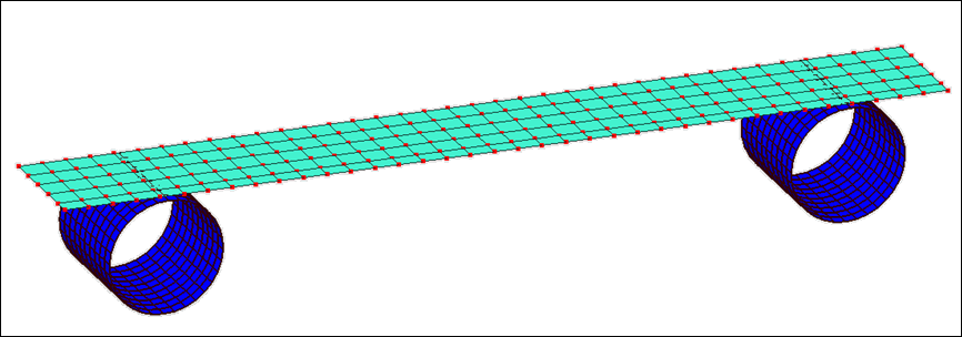
This tutorial demonstrates how to set up a 3-point bending model with symmetric boundary conditions in Y direction (across the XZ plane).
Model Description
| • | UNITS: Length (mm), Time (s), Mass (ton), Force (N) and Stress (MPa) |
| • | Simulation time: in Rootname_0001.rad [0 – 7.0E-2s] |
| • | Only one half of the model is modeled because it is symmetric. |
| • | The supports are totally fixed. An imposed velocity of 1000 mm/s is applied on the Impactor in the (–Z) direction |
| • | Model size = 370mm x 46.5mm x 159mm |
| • | Honeycomb Material /MAT/LAW28: HONEYCOMB |
[Rho_I] Initial density = 3.0e-10 ton/mm3
[E11], [E22] and [E33] Young’s modulus (Eij) = 200 MPa
[G11], [G22] and [G33] Shear modulus (Gij) = 150 MPa
|
| • | Elasto-Plastic Material /MAT/LAW36: Inner, Outer and Flat |
[Rho_I] Initial density = 7.85-9 ton/mm3
[E] Young’s modulus = 210000 MPa
[nu] Poisson's ratio = 0.29
|
|
0
|
1
|
2
|
3
|
4
|
5
|
6
|
7
|
8
|
9
|
STRAIN
|
0
|
0.010
|
0.013
|
0.015
|
0.020
|
0.025
|
0.030
|
0.035
|
0.040
|
0.045
|
STRESS8E-
|
300
|
310
|
320
|
330
|
340
|
350
|
360
|
370
|
380
|
400
|
| • | Elastic Material /MAT/PLAS_JOHNS: Impactor |
[Rho_I] Initial density = 8e-9 ton/mm3
[E] Young’s modulus = 208000 MPa
[nu] Poisson's ratio = 0.29
|
Step 1: Import the RADIOSS mesh model
| 2. | For User profile:, select RADIOSS V14. |
| 3. | For Unit system:, select N mm s T. |
| 4. | Select User interface style as New. |
| 6. | Click File > Import > RADIOSS. |
| 7. | In the input window, navigate to the correct directory and select BENDING_0000.rad. |
Step 2: Create and assign a material
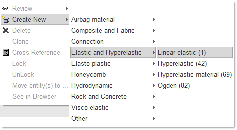
| 1. | Click Model > Material. |
| 2. | In the Window, right-click and select Create New > Elastic > Linear elastic (1) as shown below: |
| 3. | For Title, enter Rigid Material. |
| 4. | Enter all the material data, as shown in the following image. |
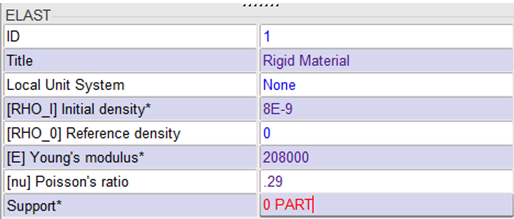
| 5. | Right-click in the entry box Support and click Include picked parts  and select the parts Impactor and Support in the graphics area. and select the parts Impactor and Support in the graphics area. |
| 6. | Click Yes in the lower right corner to validate. |
| 7. | Press ENTER or click Save to validate. |
Step 3: Create and assign a material for Inner, Outer, and Flat parts
| 1. | In the Window, right-click and select Create New > Elasto-plastic > Piecewise linear (36). |
| 2. | For Title, enter Shell Material. |
| 3. | Enter all the material data, as shown in the following image: |
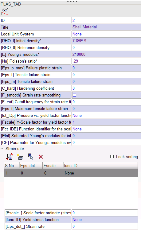
| 4. | Open the Strain rate folder and click  to add a row. to add a row. |
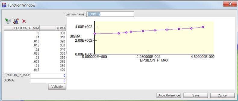
| 5. | Right-click in Yield stress function field and click Select in Model to select an existing function in the model. |
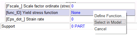
| 6. | In the Function file window, select the function with an ID of 2, then click OK to import the curve. The function can be edited, as shown in the image below. |
| 7. | Click the Tree tab and select the parts Inner, Outer, and Flat on the tree. |
| 8. | Click  to isolate this part. to isolate this part. |
| 9. | Click the Material tab. |
| 10. | Right-click the entry box Support, and click Include picked parts in the graphic area, and select the parts Inner, Outer and Flat in the graphics area as shown in the following image. |
| 11. | Click Yes in the lower right corner to validate. |
| 12. | Press ENTER or click Save to validate. |
Step 4: Create and assign a new material for HCFoam
| 1. | In the Window, right-click and select Create New > Honeycomb > Honeycomb orthotropic (28). |
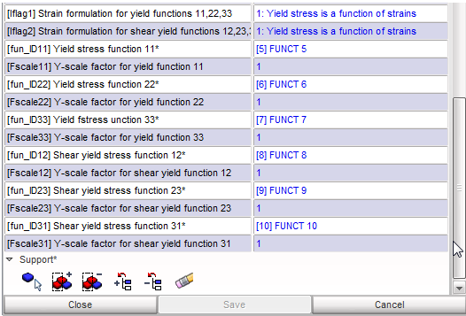
| 3. | Enter all the material data, as shown in the following image: |
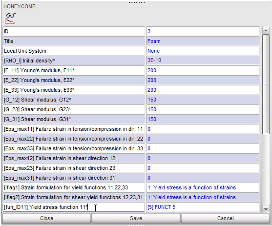
| 4. | Right-click on the Yield stress function 11 field and click Select in Model to select a curve already present in the model. |
| 5. | In the Function file window, select the function with ID of 5, then select OK. |
| 6. | Repeat this process for the Yield functions, as shown in the following image. |
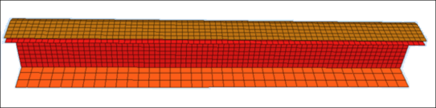
| 7. | Click the Tree tab and select the part HCFoam (7) on the tree. |
| 8. | Click to show only this part. |
| 9. | Click the Material tab. |
| 10. | Right-click in the entry box Support, and click Include picked parts to select the part HCFoam in the graphics area as shown in the following image. |
| 11. | Click Yes in the lower right corner. |
Step 5: Create and assign a property
| 1. | Click Model > Property. |
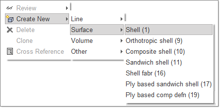
| 2. | In the Window, right-click and select Create New > Surface > Shell (1), as shown below. |
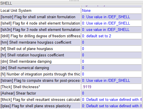
| 3. | For Title, enter Shell Property. |
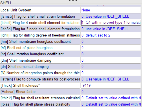
| 4. | Enter Shell thickness and Shell element formulation values, as shown in the following image. |
| 5. | Click the Tree tab and select the parts Inner, Outer and Flat on the tree. |
| 6. | Click to show only these parts. |
| 7. | Click the Property tab. |
| 8. | Right-click in the entry box Support, and click Include picked parts to select the parts Inner, Outer and Flat in the graphics area to assign Shell property. |
| 9. | Click Yes in the lower right corner. |
Step 6: Create and assign a property for Impactor and Support
| 1. | For Title, enter Rigid Property. |
| 2. | Enter the Shell thickness value as .9119, as shown in the following image. |
| 3. | Click the Tree tab and select the parts Impactor and Support in the tree. |
| 4. | Click to show only these parts. |
| 5. | Click the Property tab. |
| 6. | Right-click in the entry box Support and click Include picked parts to select the parts Impactor and Support in the graphics area to assign Rigid property. |
| 7. | Click Yes in the lower right corner. |
Step 7: Create and assign a property for HCFoam
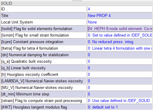
| 1. | In the Window, right-click and select Create New > Volume > General solid (14). |
| 3. | Click the Tree tab and select the part HCfoam on the tree. |
| 4. | Click to show only this part. |
| 5. | Go back to the Property tab. |
| 6. | In the Flag for solid elements formulation, select HEPH. |
| 7. | Right-click in the entry box Support and click Include picked parts to select HCfoam in the graphics area to assign Foam property. |
| 8. | Click Yes in the lower right corner. |
Step 8: Create rigid body for Impactor
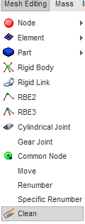
| 1. | From the menu bar, click Mesh Editing > Rigid Body. |
| 2. | In the window, right-click to select Create New, enter the name Impactor. |
| 3. | Click the Tree tab and select the Impactor assembly on the tree. |
| 4. | Click to show all parts. |
| 5. | Click the Mesh Editing tab. |
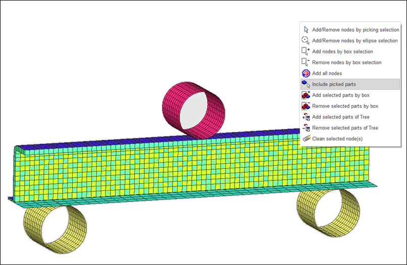
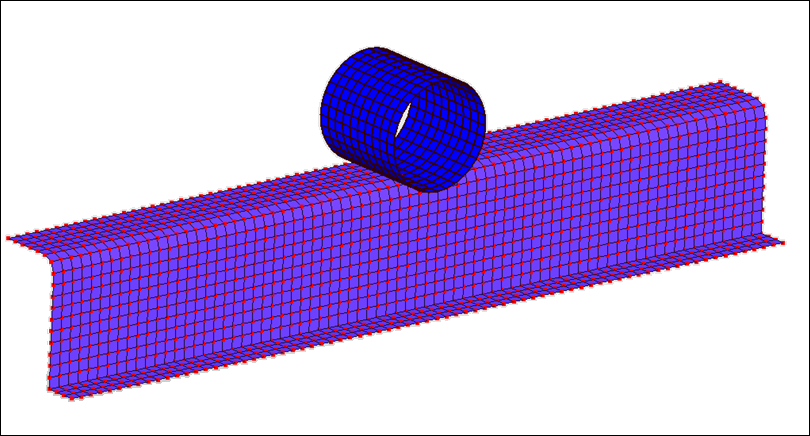
| 6. | Right-click in the entry box Support and right-click in the graphic area (as shown below). Select Include picked parts option to select Impactor in graphic area. |
Step 9: Create rigid body for Support
| 1. | In the Title field, enter the name Support. |
| 2. | Click in the entry box Support and right-click in the graphic area. Click Include picked parts option to select Support in the graphic area. |
| 3. | Click Yes to complete the selection. |
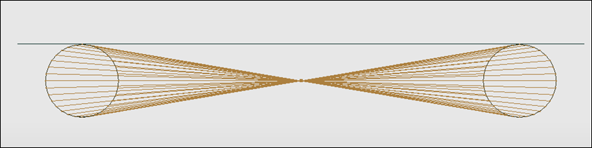
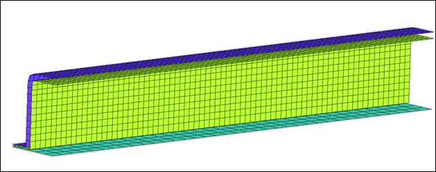
| 4. | Click Save. The rigid body for Support should look like the following image. |
Step 10: Define boundary conditions for the model
| 1. | Click LoadCase > Boundary Condition. |
| 2. | In the window, right-click to select Create New. |
| 3. | Press F6 to show the rigid bodies. |
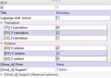
| 4. | In the Title field, enter Boundary. |
| 5. | Right-click in the entry box Support and right-click in the graphic area. Click Add/Remove nodes by picking selection and select the master node of the rigid body. |
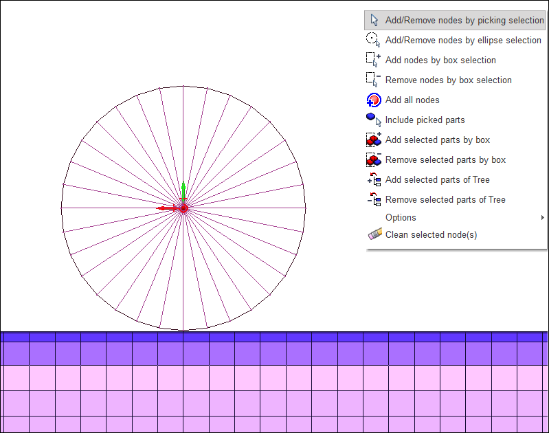
| 6. | Constrain all DOF except translation in Z as shown in the following image. To constrain the nodes, check the boxes for TX, TY, RX, RY and RZ. |
| 8. | Repeat the same process to create boundary conditions for the Support and Symmetry boundary condition for the inner/outer/flat. |
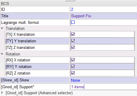
| 9. | Click node selection icon  to select master node of Support, as shown in the following image. to select master node of Support, as shown in the following image. |
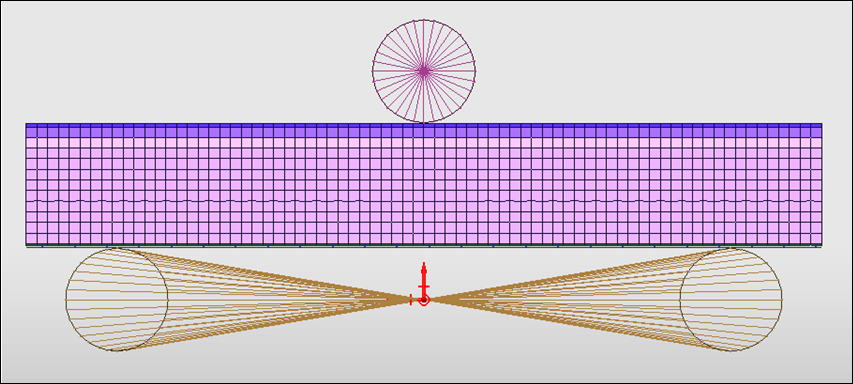
| 10. | Constrain all DOF by selecting TX, TY, TZ, RX, RY and RZ, as shown in the following image. |
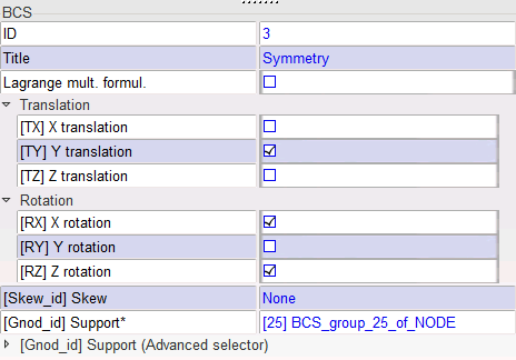
| 12. | In the Boundary condition creation field, enter Symmetry. |
| 13. | Click the Tree tab and select the parts Inner, Outer, HCfoam and Flat on the tree. |
| 14. | Click to show only these parts. |
| 15. | Press the p key to change the perspective visualization. |
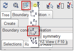
| 16. | Click the Boundary Condition tab. |
| 17. | From the Visualization toolbar, select the YZ View, as shown below. |
| 18. | Right-click in the entry box Support, right-click in the graphic window, and click Add nodes by box selection to select the nodes, as shown in the image below |
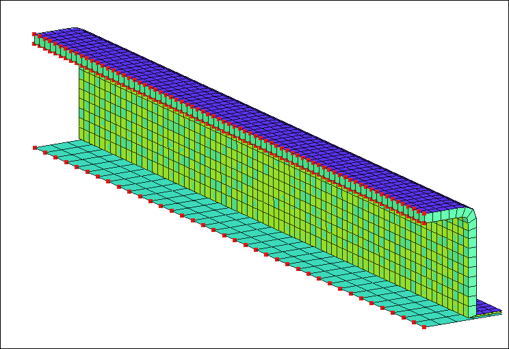
| 19. | To constrain the nodes, select TY, RX and RZ. |
Step 11: Define Impactor Velocity
| 1. | Click LoadCase > Imposed > Imposed Velocity. |
| 2. | In the window, right-click to select Create New. |
| 3. | For Title, enter IMPOSED VELOCITY. |
| 4. | For Direction, select Z (translation) and -1000 for Y-Scale factor. |
| 5. | For Time function, use the predefined curve in the model Funct 1. |
| 6. | For Y Scale factor, enter -1000. |
| 7. | Press the F6 key to show the rigid bodies. |
| 8. | Click in the entry box Support and right-click in the graphic area. Click  and select the master node of Impactor. and select the master node of Impactor. |
| 9. | Click Yes in the lower-right corner. |
Step 12: Define contacts for the model
| 1. | Click LoadCase > Contact Interface. |
| 2. | In the window, right-click and select Create New > Multi usage (Type 7). |
| 3. | Click on the check box next to Create symmetric interface at saving. |
| 4. | For Title, enter Support. |
| 5. | Click the Tree tab and select the parts Flat and Support on the tree. |
| 6. | Click to show only these parts. |
| 7. | Click the Contact Interface tab. |
| 8. | Set Min gap for impact active to 0.2. |
| 9. | Set Coulomb friction to 0.1. |
| 10. | Set [Iform] Friction penalty formulation at 2 [Stiffness]. |
| 11. | Click in the Slave nodes entry box and right-click in the graphic window. A menu appears, click Include Picked Parts and select the FLAT. |
| 12. | Press Y or click Yes at the bottom right of the screen. HyperCrash will automatically move to the selection of the Master surface. |
| 13. | Right-click and click Include Picked Parts and select the Support. |
| 14. | Press Y or click Yes at the bottom right of the screen. |
| 16. | Repeat the same process to create contact between Outer and Impactor. |
| 17. | Click the Tree tab and select the parts Outer and Impactor on the tree. |
| 18. | Click to show only these parts. |
| 19. | Right-click in the window and select Create New > Multi usage (Type 7). |
| 20. | Click the Contact Interface tab. |
| 21. | Click on the check box next to Create symmetric interface at saving. |
| 22. | In the Title, enter Imp_Outer. |
| 23. | Set Min gap for impact active to 0.2. |
| 24. | Set Coulomb friction to 0.1. |
| 25. | Set [Iform] Friction penalty formulation to 2 [Stiffness]. |
| 26. | Select Outer Part as Slave and Impactor as Master, as shown in the following image. |
| 28. | Repeat the same process for self impact for Outer, Inner and Flat, as self impact. |
| 29. | Click the Tree tab and select the parts Outer, Inner and Flat on the tree. |
| 30. | Click to show only these parts. |
| 31. | Click the Contact Interface tab. |
| 34. | Set the Min gap for impact active to 0.7. |
| 35. | Set the Coulomb friction to 0.1. |
| 36. | Set [Iform] Friction penalty formulation to 2 [Stiffness]. |
| 37. | Select components Outer, Inner and Flat, as shown in the following image. |
Step 13: Clean the model
| 1. | Click Mesh Editing > Clean. |
Step 14: Export the model
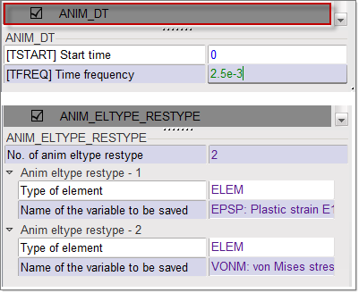
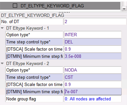
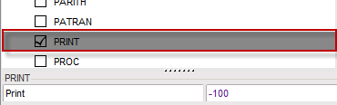
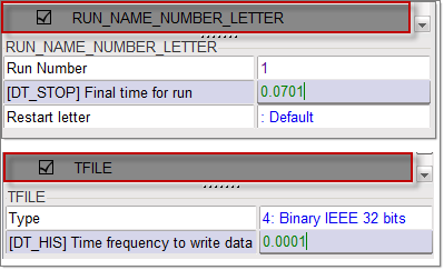
| 1. | Click Model > Control Card and select the control cards in the images below. |
| Note: | Make sure to save each control card before editing the next. |
|
| 2. | Click File > Export > RADIOSS. |
| 3. | In the Output window that opens, enter the name 3PBENDING and click OK. |
| 4. | Leave the Header of RADIOSS File window empty and click Save Model. |
The Starter file 3PBENDING_0000.rad is written.
Step 15: Open RADIOSS Manager from windows Start menu
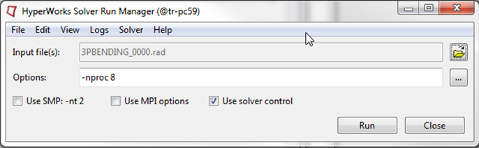
Step 16: Run the model 3PBENDING_0000.rad using RADIOSS Manager in the class_exercise folder
Step 17: Review the listing files for this run and verify on the results
| 1. | Using HyperView, plot the displacement and strain contour. |
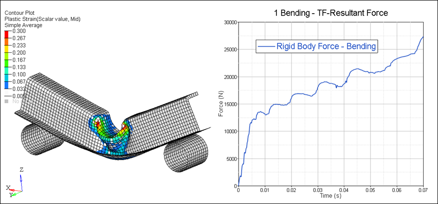
Plastic Strain Simple Average and Rigid Body Force (Impactor)
See Also:
RADIOSS Tutorials
HyperCrash User's Guide


