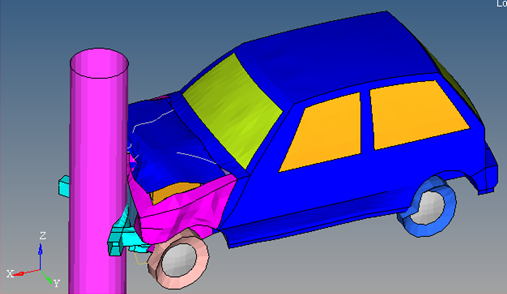
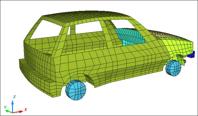
To simulate frontal pole test with a simplified full car.
Model Description
| • | UNITS: Length (mm), Time (s), Mass (ton), Force (N) and Stress (MPa) |
| • | Simulation time: Engine file (_0001.rad) [0 – 0.06 ms] |
| • | An initial velocity of 15600 mm/s is applied on the car model to impact a rigid pole of radius 250 mm. |
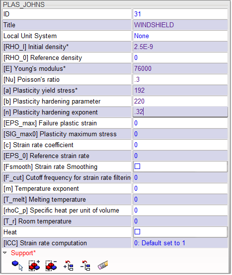
| • | Elasto-plastic Material /MAT/PLAS_JOHNS (WINDSHIELD) |
[Rho_Initial] Initial Density = 2.5x10⁻⁹ ton/mm3
[E] Young's Modulus = 76000 MPa
[nu] Poisson’s Ratio = 0.3
[ 0] Yield Stress = 192 MPa
[K] Hardening Parameter = 220 MPa
[n] Hardening Exponent = 0.32
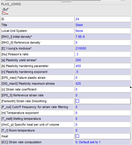
| • | Elasto-plastic Material /MAT/PLAS_JOHNS (STEEL) |
[Rho_Initial] Initial Density = 7.9x10⁻⁹ ton/mm3
[E] Young's Modulus = 210000 MPa
[nu] Poisson’s Ratio = 0.3
[0] Yield Stress = 200 MPa
[K] Hardening Parameter = 450 MPa
[n] Hardening Exponent = 0.5
[SIG_max] Maximum Stress = 425 MPa
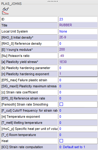
| • | Elasto-plastic Material /MAT/PLAS_JOHNS (RUBBER) |
[Rho_Initial] Initial Density = 2x10⁻⁹ ton/mm3
[E] Young's Modulus = 200 MPa
[nu] Poisson’s Ratio = 0.49
[0] Yield Stress = 1e30 MPa
[n] Hardening Exponent = 1
Exercise
Step 1: Retrieve the HyperMesh file
| 1. | Open HyperCrash and set the User profile: to RADIOSS V14 and the Unit system: to kN mm ms. kg. |
| 2. | Set User Interface style as New. |
| 3. | Set the working directory to <install_directory>/tutorials/hwsolvers/radioss. |
| 5. | Click File > Import > Nastran. |
| 6. | In the input window, select full_car.nas. |
Step 2: Create WINDSHIELD material and assign to car windows
| 1. | Click Model > Material. |
| 2. | In the Material list, right-click and select Create New > Elasto-Plastic > Johnson-Cook (2). |
| 3. | For Title, enter WINDSHIELD. |
| 4. | Enter all the material data, as shown in the image below. |
| 5. | Click the Tree tab and select PSHELL3 and PSHELL16 in the tree. |
| 6. | Click  to show only these parts. to show only these parts. |
| 7. | Click the Material tab. |
| 8. | Right-click in the Support entry box and click Selected Parts of Tree  . This icon allows adding the part selected in the tree to the selection. The selected parts will be highlighted in the graphic area. . This icon allows adding the part selected in the tree to the selection. The selected parts will be highlighted in the graphic area. |
Step 3: Create RUBBER material and assign to car tires
| 1. | In the Material list, right-click and select Create New > Elasto-Plastic > Johnson-Cook (2). |
| 2. | For Title, enter RUBBER. Enter all the material data, as shown in the image below. |
| 3. | Click the Tree tab and select PSHELL20 to PSHELL23 in the tree. |
| 4. | Click to show only these parts. |
| 5. | Click the Material tab. |
| 6. | Right-click in the Support entry box and click Selected Parts of Tree . The selected parts will be highlighted in the graphic area. |
Step 4: Create STEEL material and assign to all other parts
| 1. | In the Material list, right-click and select Create New > Elasto-Plastic > Johnson-Cook (2). |
| 2. | For Title, enter STEEL. |
| 3. | Enter all the material data, as shown in the image below. |
| 4. | Click the Tree tab and select PSHELL3, PSHELL16 and PSHELL20 to PSHELL23 in the tree. |
| 5. | Click  to invert the tree selection. to invert the tree selection. |
| 6. | Click to show all the parts except the ones made with glass and rubber. |
| 7. | Click the Material tab. |
| 8. | Right-click in the Support entry box and click Selected Parts of Tree . The selected parts will be highlighted in the graphic area. |
Step 5: Create a rigid wall to represent the ground
| 1. | Click LoadCase > Rigid Wall > Create. |
| 2. | Under Rigid wall name > Select RWALL type, select Infinite Plane. |
| 3. | Enter the rigid wall name, Ground. |
| 4. | Enter the following values for M0 and M1: |
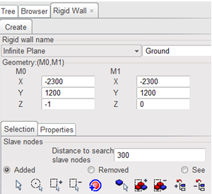
| 5. | In the Selection tab, set the Distance to search for slave nodes to 300. |
| 6. | Click See at the bottom of the panel to display the rigid wall. |
Step 6: Create Pole Rigid Walls
| 1. | Under Rigid wall name > Select RWALL type, select Cylinder. |
| 2. | Enter the rigid wall name, Pole. |
| 3. | Enter the following values for M0 and M1: |
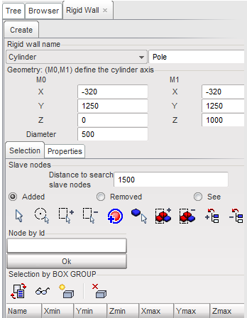
| 4. | Set the Diameter to 500. |
| 5. | Set the Distance to search for slave nodes to 1500. |
| 6. | Click See at the bottom of the panel to display the rigid cylinder. |
| 8. | Click Close to close the Rigid Walls panel. |
Step 7: Define interface with the whole car
| 1. | Click LoadCase > Contact Interface. |
| 2. | In the window right-click and select Create New > Multi usage (Type 7). |
| 3. | Select the Self Impact box. |
| 4. | In the Title field, enter CAR_CAR. |
| 5. | Set [Istf] Stiffness definition to 2: (K=(Km+Ks)/2. |
| 6. | For [Gapmin] Min. gap for impact activ., enter 0.7. |
| 7. | For [Fric] Coulomb friction, enter 0.2. |
| 8. | Set [Iform] Friction penalty formulation to 2: (Stiffness). |
| 9. | In the Model Display toolbar, click Display All  to display the entire model. to display the entire model. |
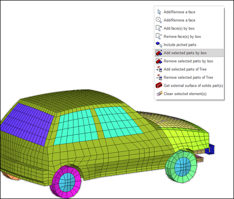
| 10. | Click in the [Mast_id] Master field. Move the cursor to the graphical window and right-click. The menu shown in the image below should appear. Choose the option Add selected parts by box  and use the mouse to drag a box to select the entire car in the graphic window. and use the mouse to drag a box to select the entire car in the graphic window. |
Step 8: Create an interface between engine and radiator
| 1. | Right-click in the Contact list and select Create New > Multi usage (Type 7). |
| 2. | Check Create symmetric interface at saving box. |
| 3. | In the Title field, enter ENGINE_RADIATOR. |
| 4. | For [Istf] Stiffness definition, set to 2 (K=(Km+Ks)/2. |
| 5. | For [Gapmin] Min. gap for impact active, enter 0.7. |
| 6. | For [Fric] Coulomb friction, enter 0.2. |
| 7. | For [Iform] Friction penalty formulation, set to 2 [Stiffness]. |
| 8. | In the Tree tab, highlight the part PSHELL28 (Radiator) and PSHELL30 (Engine) and Isolate them. |
| 9. | In the Contact Interface tab, click in the [Slav_id] Slave nodes field, move the cursor to the graphic window, right-click and select Include picked Part. Select the Radiator (PSHELL28). |
| 10. | In the Contact Interface tab, click in the [Mast_id] Master Surface field, move the cursor to the graphic window, right-click and select Include picked Part. Select the Engine (PSHELL30). |
| 12. | Click Close to close the Contact tab. |
An additional symmetric interface is created.
Step 9: Define Initial Velocities
| 1. | Click LoadCase > Initial Velocity. |
| 2. | In the Velocity list, right-click and select Create New. |
| 3. | In the Title field, enter 35MPH. |
| 4. | In the Tree window, highlight FULL_CAR. |
| 5. | In the [Vx] field, enter 15600. |
| 6. | In the Initial Velocity tab and click in the [Gnod_id] Support field. Move the cursor to the graphic window, right-click and select Add selected parts of tree . |
Step 10: Define Time History Nodes
| 1. | Click Data History > Time History. |
| 2. | In the Time History list, right-click and select Create New > TH of nodes. |
| 4. | In the Tree tab, select PSHELL19. |
| 5. | Click Isolate Tree Selections . |
| 6. | Go back to the Time History panel and click Add/Remove nodes by picking selection  in the second table. in the second table. |
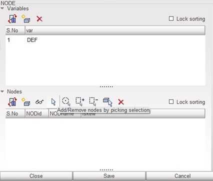
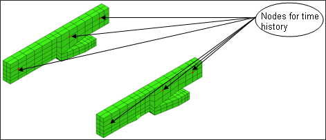
| 7. | Select six nodes on the rails, for example as shown in the following image: |
| 7. | Click Yes in the lower right corner or right-click in the graphic window to exit the selection. |
Step 11: Export the model
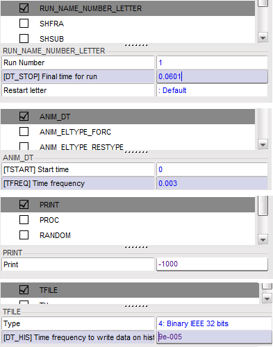
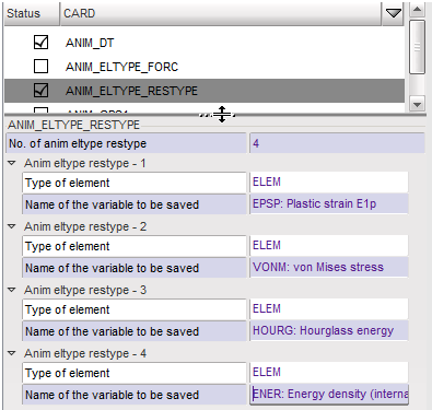
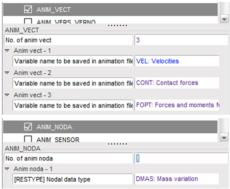
| 1. | Create the Engine file: From the menu bar, select Model > Control Card. |
| 2. | Check the Control Cards, as shown in the images below. |
| Note: | Make sure to save all control card before editing the next. |
|
| 3. | Under the Quality menu, click Model Checker to check the quality, then check All Solver Contact interfaces, remove all the initial penetrations in the model. |
| 4. | Under Mesh Editing menu, click Clean, then clean the model before exporting. |
| 5. | Click File > Export > RADIOSS, enter FULLCAR and click OK. |
| 6. | Leave the Header of RADIOSS File window empty and click Save Model. The Starter file FULLCAR_0000.rad is written. |
Step 12: Open RADIOSS from Windows Start menu
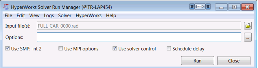
Step 13: Select the Starter file FULLCAR_0000.rad as Input file and Run the model
Exercise Expected Results
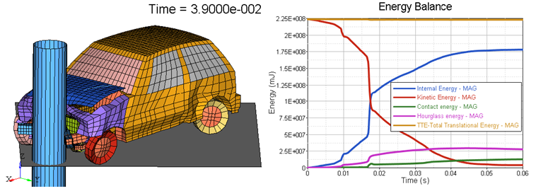
Final deformation and energy balance plot
See Also:
RADIOSS Tutorials
HyperCrash User's Guide


