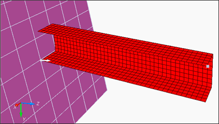
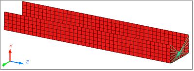
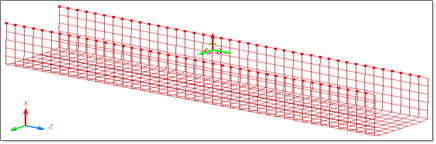
Simulate buckling of a tube using half tube mesh with symmetric boundary conditions.
The figure illustrates the structural model used for this tutorial: a half tube with a rectangular section (38.1 x 25.4 mm) and length of 203 mm.
Model
Model Description
| • | UNITS: Length (mm), Time (ms), Mass (kg), Force (kN) and Stress (GPa) |
| • | Simulation time: Engine [0 – 10 ms] |
| • | The tube thickness is 0.914 mm. |
| • | An imposed velocity of 13.3 mm/ms (~30 MPH) is applied to the right end of the tube |
| • | Elasto plastic material using Johnson-Cook law /MAT/PLAS_JOHNS (STEEL). |
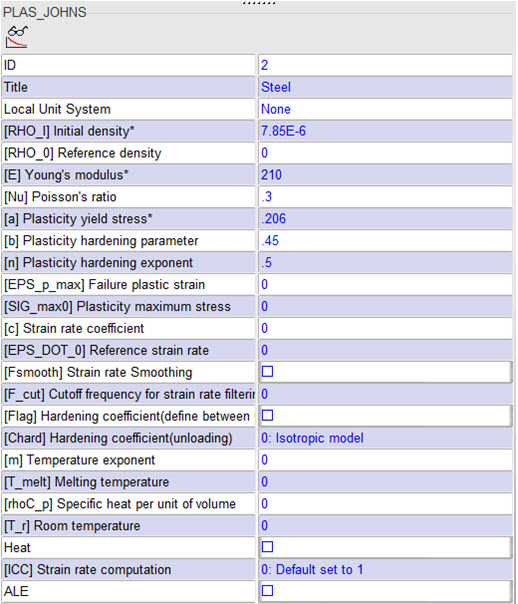
[Rho_Initial] Initial density = 7.85e-6 Kg/mm3
|
[E] Young’s modulus = 210 GPa
|
[nu] Poisson coefficient = 0.3
|
[a] Yield Stress = 0.206 GPa
|
[b] Hardening Parameter = 0.450 GPa
|
[n] Hardening Exponent = 0.5
|
File needed to complete this exercise: BOXTUBE_0000.rad
Exercise
Step 1: Import the mesh
| 1. | Open HyperCrash and set the User profile: to RADIOSS V14 and the Unit system: to kN mm ms kg. |
| 2. | Set User interface style as New. |
| 3. | Set the working directory to <install_directory>/tutorials/hwsolvers/radioss/. |
| 5. | Click File > Import > RADIOSS. |
| 6. | In the input window, select BOXTUBE_0000.rad. |
Step 2: Create and assign a material
| 1. | Click Model > Material. |
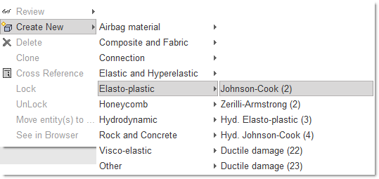
| 2. | In the window, right-click and choose Create New > Elasto-plastic > Johnson-Cook (2). |
| 3. | For Title, enter Steel. |
Enter all the material data, as shown in the following figure.
| 4. | Right-click in Support entry box and click Select in graphics and select Include picked parts  and select boxtube in the graphics area. and select boxtube in the graphics area. |
| 5. | Press ENTER, or click Yes in the lower right corner. |
Step 3: Create and assign a property
| 1. | Click Model > Property. |
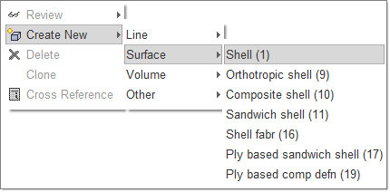
| 2. | In the window, right-click and select Create New > Surface > Shell (1). |
| 3. | For Title, enter Pshell. |
| 4. | For Shell thickness, enter 0.914. |
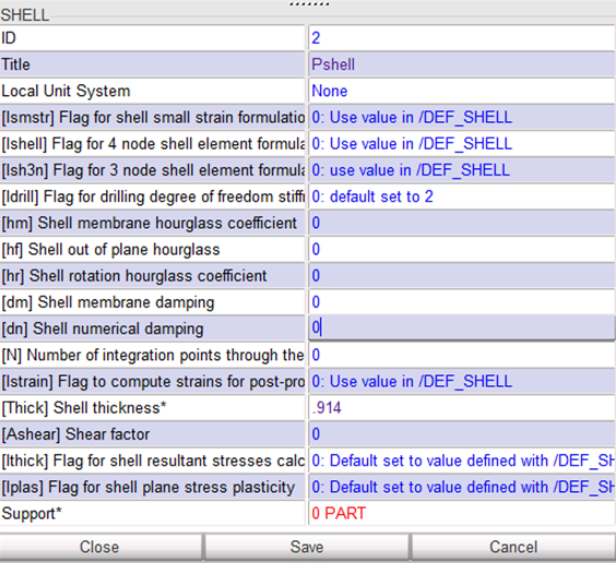
| 5. | Right-click in the Support entry box and click Select in graphics and select Include picked parts and select boxtube in the graphics area. |
| 6. | Press ENTER or click Yes in the lower right corner. |
Step 4: Define Rigid Body
| 1. | Click Mesh Editing > Rigid Body. Right-click in the display list area and select Create New. |
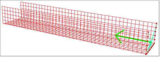
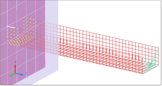
| 2. | Right-click in the graphic area and select Add nodes by box selection icon  to select the nodes in the graphic window, as shown below: to select the nodes in the graphic window, as shown below: |
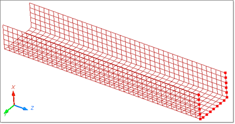
| 3. | Press ENTER or click Save to validate. |
| Note: | For the remainder of the tutorial, you need to have the ID of the master node of the rigid body. |
|
| 4. | Click Show Node Info icon  in the toolbar, and select the rigid body master node in the graphic window. The Node ID appears in the message window (node ID: 803). in the toolbar, and select the rigid body master node in the graphic window. The Node ID appears in the message window (node ID: 803). |
| 5. | Click Cancel in the lower right corner to exit the picking loop. |
Step 5: Define boundary condition applied on rigid body
| 1. | Click LoadCase > Boundary Condition. |
| 2. | Right-click in the display list area and select Create New. |
| 3. | In the Boundary condition field, enter the name Rigid_BC. |
| 4. | In the Node by Id field, enter 803, then click Ok. |
| 5. | To constrain the nodes, toggle the buttons in Tx, Ty, Rx, Ry and Rz. |
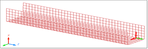
Step 6: Define boundary condition representing symmetry
| 1. | In the Boundary condition display list area, select Create New. Name the new constraint set symmetry. |
| 2. | Right-click in the Support entry box and click Select in graphics and select Add nodes by box selection icon to select the nodes in the graphic window, as shown below: |
| 3. | Right-click to validate. |
| 4. | Toggle the buttons Tx, Ry and Rz. |
Step 7: Define the imposed velocity
| 1. | Click LoadCase > Imposed Velocity. Right-click in the display list area and select Create New. |
| 2. | For Title, enter VELOCITY. |
| 3. | Right-click in the Time function parameter entry box and select Define New. A Function Window opens. |
| 4. | For the function name, enter FUNC_VEL. |
| 5. | Enter the first point (0, 13.3) and click Validate. |
| 6. | Enter the second point (1e30, 13.3) and click Validate. |
| 7. | Click Save in the Function Window to accept the function. |
| 8. | Expand the Advanced selector at the bottom and in the Node by Id field, enter 803 and click Ok, (or toggle Add RB master nodes). |
| 9. | Go to the Properties tab and enter a Y-Scale factor = -1. |
| 10. | Set the direction of the imposed velocity to Z (translation). |
Step 8: Define a Rigid Wall
| 1. | Click LoadCase > Rigid Wall > Create. |
| 2. | For the Select RWALL, select Infinite Plane. |
| 3. | For Title, enter RIGID WALL. |
| 4. | Enter the following values: M0: X= 0, Y= 38.1, Z= -204. M1: X= 0, Y= 38.1, Z= 1. |
| 5. | In the Distance to search slave nodes field, enter 20. |
| 7. | Click See to visualize it in the graphic window. |
Step 9: Create a self contact for the tube
| 1. | Click LoadCase > Contact Interface. |
| 2. | Right-click in the Contact Interface list and select Create New > Multi usage (Type 7). |
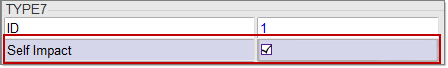
| 4. | Right-click in the graphic area, and select Include picked parts icon and select the part in the graphic window. |
| 5. | Click Yes in the lower right corner of the main window to validate. |
| 6. | For Title, enter the name Contact. |
| 7. | Set Scale factor for stiffness as 1. |
| 8. | Set Min. gap for impact active to 0.900. |
| 9. | Set Coulomb friction to 0.200. |
Step 10: Export the model
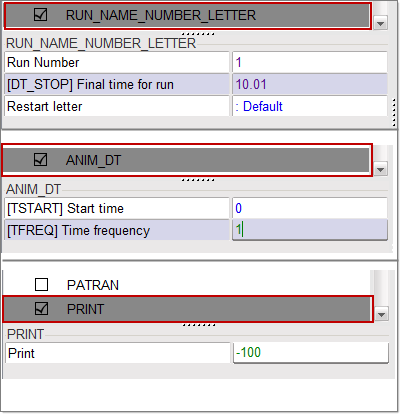
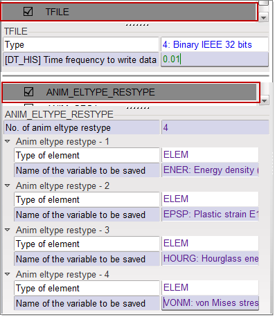
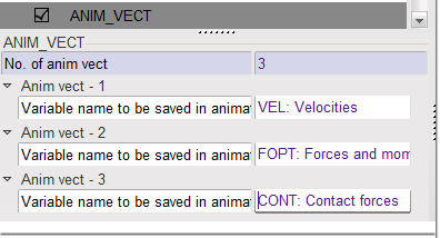
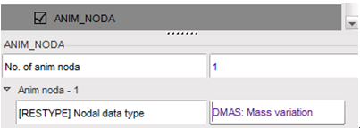
| 1. | Under the Model menu, select Control Card. |
| 2. | Check Control Card to activate it. |
| Note: | Make sure to save it before moving to the next Control Card. |
|
| 3. | Click File > Export > RADIOSS. |
| 4. | In the Write Block Format 140 RADIOSS File window that opens up, enter the name BOXTUBE and click OK. |
| 5. | Leave the Header of RADIOSS File window empty and click Save Model. |
The Starter file BOXTUBE_0000.rad is written.
The model is now ready to run through the Starter and the Engine.
Step 11: Open RADIOSS from Windows Start menu
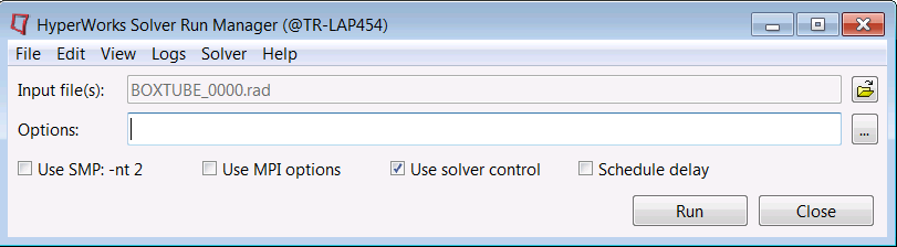
Step 12: Review the listing files for this run and verify on the results
| 1. | Using HyperView, plot the displacement and strain contour at 10 ms. |
Exercise Expected Results
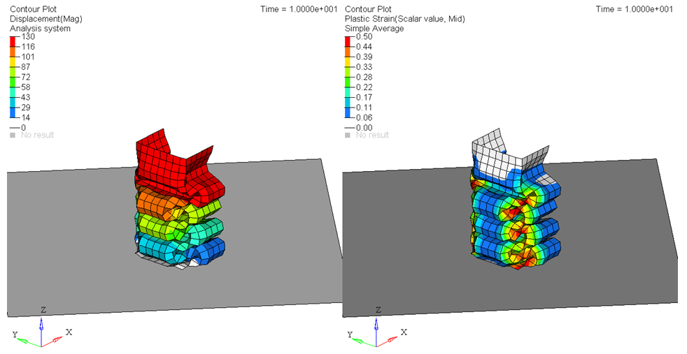
Total Displacement (mm) and Plastic Strain (Mid Layer and Average)
See Also:
RADIOSS Tutorials
HyperCrash User's Guide


