|
»Click here to display Table of Contents«
|

Reference: Marker |

|

|

|

|
|
Reference: Marker |
|
|

|

|
|
»Click here to display Table of Contents«
|
Reference: Marker |
|
|
|
|
|
Reference: Marker |
|
|
|
|
Model Element |
|||||||||||||||||
Description |
|||||||||||||||||
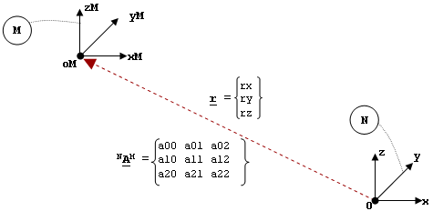
A Reference_Marker defines an orthonormal, right-handed coordinate system and reference frame in MotionSolve. A Reference_Marker must belong to a body. The body can be any type: rigid, flexible, or point. The Newtonian reference frame (Ground) is considered to be a special case of a rigid body. The image below illustrates how a Reference_Marker is defined. Defining a Reference_Marker on Ground In the image above, N represents the Newtonian reference frame and coordinate system. It consists of a global origin O and three right-handed, mutually perpendicular directions denoted as OX, OY, and OZ. M represents another coordinate system of interest. The origin of M is denoted by oM, and the axes of M are denoted as xM, yM, and zM. For this example, assume M is fixed with respect to N. To define M, the measure numbers of the vector O-oM in the coordinate system N are needed. This is denoted as r in the image. The rotation matrix that converts from the xM-yM-zM basis to the x-y-z basis is needed. This is denoted as NAM in the image. A Reference_Marker is defined by specifying the following:
Common uses for Reference_Markers in MotionSolve include:
The Reference_Marker with id = 0 has special significance. In all MotionSolve expressions, it is used to denote the global coordinate system. The attribute node_id is optional. It is used only for flexible bodies. |
|||||||||||||||||
Format |
|||||||||||||||||
<Reference_Marker id = "integer" [ label = "string" ] body_id = "integer" [ body_type = {"RIGIDBODY" | "FLEXBODY" | "POINTBODY"} ] [ rm_id = "integer" ] [ node_id = "integer" ] { pos_x = "real" pos_y = "real" pos_z = "real" [{ a00 = "real" a10 = "real" a20 = "real" a01 = "real" a11 = "real" a21 = "real" a02 = "real" a12 = "real" a22 = "real" | psi = "real" theta = "real" phi = "real" | yaw = "real" pitch = "real" roll = "real" | e0 = "real" e1 = "real" e2 = "real" e3 = "real" }] } | { usrsub_param_string = "USER(..,..)" usrsub_fnc_name = "valid fnc name" usr_dll_name = "valid dll name" | usrsub_param_string = "USER(..,..)" usrsub_fnc_name = "valid fnc name" interpreter = "PYTHON | MATLAB" script_name = "valid script name" } /> |
|||||||||||||||||
Attributes |
|||||||||||||||||
id |
Element identification number (integer>0). This number is unique to all Reference_Marker elements. |
||||||||||||||||
label |
The name of the Reference_Marker element. |
||||||||||||||||
body_id |
ID of the body to which marker belongs. The body may be Ground, a rigid body, a point mass, or a flexible body. |
||||||||||||||||
body_type |
Specifies whether the body is of type RIGIDBODY, FLEXBODY or POINTBODY This parameter is optional. The default type is RIGIDBODY. |
||||||||||||||||
rm_id |
An optional attribute that specifies the Reference_Marker ID. If specified, the position and orientation of the marker is assumed to be with respect to the reference marker. The default ID is 0 which refers to the global reference frame. |
||||||||||||||||
node_id |
An optional attribute used only for flexible bodies. |
||||||||||||||||
pos_x, pos_y, pos_z |
The x, y, z coordinates of the marker origin specified in terms of the global frame. pos_x defines the x-coordinate of the origin, pos_y defines the y-coordinate of the origin, and pos_z defines the z-coordinate of the origin. |
||||||||||||||||
a00 a01 a02 a10 a11 a12 a20 a21 a22 |
Elements of the transformation matrix defining the orientation of the Reference_Marker with respect to the global frame. {a00 a10 a20} defines directions cosines of the x-axis {a01 a11 a21} defines directions cosines of the y-axis {a02 a12 a22} defines directions cosines of the z-axis. The nine elements define a 3x3, orthonormal matrix. This means that the nine numbers must satisfy the following conditions:
|
||||||||||||||||
psi |
In radians, the rotation around the original z-axis. |
||||||||||||||||
theta |
In radians, the rotation around the new x-axis after Psi has been applied. |
||||||||||||||||
phi |
In radians, the rotation around the new z-axis after Theta has been applied. |
||||||||||||||||
yaw |
In radians, the rotation around the original z-axis of the marker. |
||||||||||||||||
pitch |
In radians, the rotation about the new location of the y-axis of the marker after yaw has been applied. |
||||||||||||||||
roll |
In radians, the rotation about the new location of the x-axis after pitch has been applied. |
||||||||||||||||
e0, e1, e2, e3 |
Euler parameters that describe the rotation. |
||||||||||||||||
usrsub_param_string |
The list of parameters that are passed from the data file to the user defined subroutine. |
||||||||||||||||
usrsub_fnc_name |
Specifies an alternative name for the user subroutine MARKER_READ. |
||||||||||||||||
usrsub_dll_name |
Specifies the path and name of the DLL or shared library containing the user subroutine. MotionSolve uses this information to load the user subroutine in the DLL at run time. |
||||||||||||||||
script_name |
Specifies the path and name of the user written script that contains the routine specified by usrsub_fnc_name. |
||||||||||||||||
interpreter |
Specifies the interpreted language that the user script is written in. Valid choices are MATLAB or PYTHON. |
||||||||||||||||
Comments |
|||||||||||||||||
|
|||||||||||||||||
Example |
|||||||||||||||||
The following example defines a Reference_Marker on a rigid body. <Reference_Marker id = "1012" body_id = "1000" body_type = "RIGIDBODY" pos_x = "1.414" pos_y = "3.14159" pos_z = "1.61804" a00 = "0." a10 = "1." a20 = "0." a01 = "0.041630503" a11 = "0." a21 = "0.99913307" a02 = "0.99913307" a12 = "0." a22 = "-0.04163050"> </Reference_Marker> In the following example, only two of the columns of the DC matrix have been specified, namely those corresponding to the X and Z axes. The third column, corresponding to the Y axis, is computed using the vector cross product between the Z and X vectors. <Reference_Marker id = "90000072" body_id = "30303" body_type = "RigidBody" pos_x = "-130." pos_y = "0." pos_z = "-50." a00 = "0." a10 = "1." a20 = "0." a02 = "0.447214" a12 = "0." a22 = "0.89442699" /> In the following example, the DC matrix is omitted, implying that it is an identity matrix. Note that pos_x, pos_y and pos_z have also been omitted, which implies that they are all zero by default. <Reference_Marker id = "90000072" body_id = "30303" body_type = "RigidBody" /> In the following example, the Reference_Marker is specified using a Python script. <Reference_Marker id = "30102040" label = "Joint 3-Marker I" body_id = "30102" body_type = "RigidBody" usrsub_param_string = "USER(1,-0.5,0.3,0.,1.57079633,1.57079633,-1.57079633)" interpreter = "Python" script_name = "script/marker_read.py" usrsub_fnc_name = "MARKER_READ" /> The script marker_read.py is defined below: def MARKER_READ(id, par, npar):
eflg = 0 errflg = 0 r = 3*[0.0] angle = 6*[0.0] angle_type = int(par[0]) r[0] = par[1] r[1] = par[2] r[2] = par[3] if angle_type==0: # DCMTX angle[0] = par[4] angle[1] = par[5] angle[2] = par[6] angle[3] = par[7] angle[4] = par[8] angle[5] = par[9] elif (angle_type == 1) | (angle_type == 2): # Euler angles (313 or YPR) angle[0] = par[4] angle[1] = par[5] angle[2] = par[6] elif angle_type == 3: # Euler parameters angle[0] = par[4] angle[1] = par[5] angle[2] = par[6] angle[3] = par[7] else: errflg = 1; return errflg
eflg = py_put_marker(id, r, angle_type, angle)
return errflg |
|||||||||||||||||
Model Element |
|
Description |
|
MARKER defines an orthonormal, right-handed coordinate system and reference frame in MotionSolve. A MARKER must belong to a part. The body can be any type: rigid, flexible, or point. The Newtonian reference frame (Ground) is considered to be a special case of a rigid PART. |
|
Declaration |
|
def MARKER(id, LABEL="", PART=0, POINT_MASS=0, FLEX_BODY=0, QP=[], ZP=[], XP=[], REULER=[],FLOATING=False, RM=0, NODE=0, USEXP=False, FUNCTION="", ROUTINE="", INTERPRETER="", SCRIPT=""): |
|
Attributes |
|
id |
Element identification number (integer>0). This number is unique among all the MARKER elements. |
LABEL |
The name of the MARKER element. |
PART |
Specifies the ID of the part to which MARKER belongs. |
POINT_MASS |
Specifies the ID of the point mass to which the MARKER belongs. |
FLEX_BODY |
Specifies the ID of the flexible part to which the MARKER belongs. |
QP |
Specifies the coordinates of MARKER with respect to RM. |
ZP |
Specifies a point with respect to RM, denoting the direction of Z axis from QP. |
XP |
Specifies a point with respect to RM, denoting the direction of X axis from QP. |
REULER |
Specifies the Euler angles of MARKER with respect to RM. |
FLOATING |
Specifies whether the MARKER is a floating marker or not. By default it is set to "FALSE". |
RM |
An optional attribute that specifies the Reference Marker ID. If unspecified, the position and orientation of the MARKER is assumed to be with respect to the LPRF of the hosting body. If specified, the position and orientation of the MARKER is assumed to be with respect to the reference marker. For example, if you want to specify the position and orientation of the MARKER in the global reference frame, use RM=0. |
NODE |
Specifies the node on the flexible body to which the MARKER is associated. |
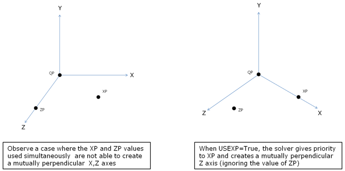
USEXP |
This attribute when set to TRUE uses the x-point-z-point method of orientation. It causes the marker to be oriented such that x-axis lies on XP, and z-axis lies in the positive xz-plane(ignoring ZP), in a situation when XP and ZP are not mutually orthogonal (as they are supposed to be). |
FUNCTION |
The list of parameters that are passed from the data file to the user defined subroutine. This attribute is common to all types of user subroutines and scripts. The name of the user subroutine depends on the type of the element. |
ROUTINE
|
Specifies an alternative name for the user subroutine.When ROUTINE is specified, the position and orientation calculated in MARKER_READ and defined in py_put_marker should be with respect to the global reference frame. In other words, the position and orientation you passed to MotionSolve via py_put_marker in MARKER_READ are assumed to be defined in the global reference frame in all cases. |
INTERPRETER |
Specifies the interpreted language that the user script is written in. Valid choices are MATLAB or PYTHON. |
SCRIPT |
Specifies the path and name of the user written script that contains the routine. |
CommentsSee Reference_Marker |
|
ExampleThe following example defines a marker on a rigid part.MARKER(1012,LABEL="Marker 2",PART=1000,QP=[1.414,3.142,1.618],ZP=[101.327,3.142,-2.545],XP=[1.414, 3.142, 101.618]) In the following example, both QP and ZP have been omitted, which implies that they are all zero by default.MARKER(90000072,LABEL="Joint 3-Marker I",PART=30303) In the following example, the Reference_Marker is specified using a Python script.MARKER(30102040,LABEL="Marker 2",PART=30102,QP=[1.414,3.142,1.618],ZP=[101.327, 3.142, -2.545],XP=[5.577, 3.142, 101.531],FUNCTION="USER(1,-0.5,0.3,0.,1.57079633,1.57079633,-1.57079633)",ROUTINE="MARKER_READ",INTERPRETER="Python",SCRIPT="MARKER_READ.py") The script marker_read.py is defined below:def MARKER_READ(id, par, npar):
|
|
See Also:
The following MDL Model statements:
*SetOrientation() - marker angles orientation
*SetOrientation() - marker dual axes orientation
*SetOrientation() - marker pair angles orientation
*SetOrientation() - marker pair dual axes orientation
*SetOrientation() - marker pair single axis orientation
*SetOrientation() - marker single axis orientation
*SetPoint() - asymmetric point pair
*SetPoint() - symmetric point pair
*SetVector() - asymmetric vector pair