|
»Click here to display Table of Contents«
|

Rigid Body (/RBODY) |

|

|

|

|
|
Rigid Body (/RBODY) |
|
|
|

|
|
»Click here to display Table of Contents«
|
Rigid Body (/RBODY) |
|
|
|
|
|
Rigid Body (/RBODY) |
|
|
|
|
A rigid body is defined by a set of slave nodes and a master node. It can be compared to a part with an infinite stiffness. No relative displacement is allowed between slave nodes, and the general motion of the rigid body manages the master node. As a kinematic condition is applied on each slave nodes and for all directions, no other nodal constraint is allowed. However, in the case of the Lagrange Multiplier method, the solution can be found if no incompatible kinematic conditions are applied.
Four options are available to position the center of gravity of the rigid body:
Case 1:
| • | COG is computed with slave and master nodes mass and coordinates |
| • | Rigid body mass is the sum of the added mass and slave node mass |
Case 2:
| • | COG is computed with slave nodes mass and coordinates only |
| • | Rigid body mass is the sum of the added mass and slave node mass |
Case 3:
| • | COG is set at master node’s coordinates |
| • | Rigid body mass is the sum of the added mass and slave node mass |
Case 4:
| • | COG is set at master node’s coordinates |
| • | Rigid body mass is equal to the added mass |
It is strongly recommended to use an artificial node (not part of an element) as a master node, since RADIOSS Starter is likely to move the master node. The master node is moved by RADIOSS Starter to the center of gravity; unless the ICoG flag is set to 3 or 4. It is advised to set ICoG to 2 to get the most realistic behavior; the center of gravity is then computed taking into account only the slave nodes. If ICoG is set to 1, the master node, with its own mass, is included to compute the center of gravity.
If the master node is initially set to the center of gravity, the behavior using ICoG = 1 or 2 is similar.
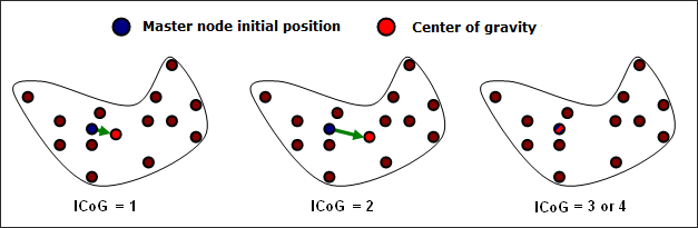
Fig. 4.1: Center of gravity computation
In a car crash simulation, rigid bodies are largely used and three typical uses of rigid bodies can be distinguished:
| • | Rigid body covering a part of a finite element model, including shells, solids or other elements: In this case, the mass of slave nodes gives the total rigid body mass and no added mass is needed. The master node can be located anywhere, and it will be moved to the center of mass. This kind of rigid body saves a large amount of CPU time. |
| • | Rigid body representing a non-modeled component connected on some structural nodes: In this case, only a few number of slave nodes are used to connect the rigid body to the finite element model. The mass and inertia are added and the master node is located at the component center of mass. The master node will only move a little, taking into account the mass of the slave nodes. In some cases, a dummy mesh is used to visualize the rigid body or to simulate the contacts, but if the dummy elements have a small mass, the previous remarks are still true. |
| • | Rigid body used to connect two or more parts together: For these rigid bodies no added mass is needed and the master node can be located anywhere. A spherical inertia must be used for these rigid bodies; as these rigid bodies are usually very small (4 to 8 nodes), the inertia is often very small in one direction and very large for one specific direction. This may lead to instability; therefore, through the use of spherical inertia, inertia will be identical for any direction. |
Rigid bodies can be activated or deactivated with a sensor or with the options /RBODY/ON and /RBODY/OFF in the Engine files.
To activate two rigid bodies with the master node 1 and 2, add the following option in Rootname_0001.rad:
/RBODY/ON
1 2
⇒ all elements included in both rigid body are deactivated.
To deactivate one rigid body whose master node ID is 3, add:
/RBODY/OFF
3
⇒ all elements are reactivated, strains and stresses are those from previous deactivation time.
One of the main uses of rigid body activation and deactivation concerns the roll-over motions, as in roll-over simulations. During the free fly of the car, the elements deformation can be neglected. A large part of CPU time can be saved if the whole structure is replaced with a temporary rigid body during the fly. Before the impact on the ground, this rigid body is deactivated and eventually activated again after rebound.
Engine
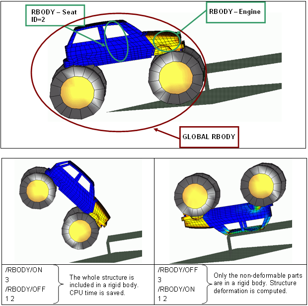
Fig. 4.2: Activation - Deactivation of Rigid Bodies in a roll-over example
Another use of rigid body activation and deactivation is for initial static equilibrium, where only gravity is applied. In a crash analysis, it may be of interest to set the whole car in equilibrium over the suspension, and the dummy on the seat. For an explicit analysis, it takes a long time to reach a static equilibrium; consequently using a large rigid body allows a solution to be obtained faster. However, in this case the deformation in a car or in a dummy under gravity is neglected and validity of this assumption needs to be carefully watched.
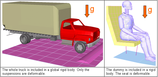
Fig. 4.3: Static equilibrium examples
Rigid body activation and deactivation is also used to set an initial rotational velocity around a specific center (or axis). The methodology is to create a global rigid body of the structure in rotation, then, the master node of this global rigid body must lie at the center of rotation. In order not to be moved, ICoG must be set to 3 (the inertia will be computed according to the slave nodes) or to 4 (the inertia is user-defined). Finally, the rotational velocity is applied to the master node. In RADIOSS Engine, a 1 cycle run must be performed with the global rigid body set to ON, and all the other rigid bodies set to OFF, so that the initial velocity for all slave nodes is:
![]()
Then, a second run is performed setting the global rigid body to OFF, and ON for all the other rigid bodies.
An application example is an initial rotational velocity of a head impact.
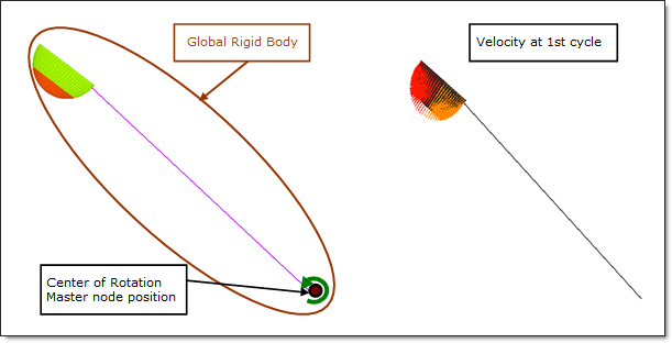
Fig. 4.4: Rotational velocity for a head impactor
|