|
»Click here to display Table of Contents«
|

UNBALNC |

|

|

|

|
|
UNBALNC |
|
|

|

|
|
»Click here to display Table of Contents«
|
UNBALNC |
|
|
|
|
|
UNBALNC |
|
|
|
|
UNBALNC – Unbalanced Load (Rotor Dynamics)
This entry defines the unbalanced rotating load during a rotor dynamic analysis in Frequency Response solution sequences. The unbalanced load is specified in a cylindrical system where the rotor rotation axis is the Z-axis.
Format
(1) |
(2) |
(3) |
(4) |
(5) |
(6) |
(7) |
(8) |
(9) |
(10) |
UNBALNC |
SID |
MASS |
GRID |
X1 |
X2 |
X3 |
|
|
|
|
ROFFSET |
THETA |
ZOFFSET |
FON |
FOFF |
|
|
|
|
|
Argument |
Options |
Description |
|||||
SID |
<Integer > 0> No default |
setid |
Set identification number. |
||||
|
|||||||
MASS |
<Integer > 0/Real> No default |
Defines the magnitude of unbalanced mass (see comment 4). |
|||||
|
|||||||
GRID |
<Integer> No default |
Grid Point identification number of node at which the unbalanced load is applied. |
|||||
|
|||||||
X1, X2, X3 |
<Real> No default |
Components of a vector that are used to define a cylindrical coordinate system centered at “GRID”. The vector components are defined from “GRID” in the displacement coordinate system of the grid point at “GRID” (see comment 6). |
|||||
|
|||||||
ROFFSET |
<Integer > 0/Real> Default = 1.0 |
<Integer > 0> |
If an integer value (must be greater than 0) is input, it references the identification number of a TABLEDi entry that specifies the offset values as a function of frequency (see comment 4). |
||||
<Real> |
This field defines the distance by which the unbalanced mass is offset in the X-Y plane perpendicular to the Z direction (spin axis, Figure 1). If a real number is input, the offset value is considered constant. |
||||||
|
|||||||
THETA |
<Real> Default = 0.0 |
Angular position (in degrees) of the unbalanced mass in the cylindrical coordinate system defined by X1, X2, and X3. |
|||||
|
|||||||
ZOFFSET |
<Integer > 0/Real> Default = 0.0 |
<Integer > 0> |
If an integer value (must be greater than 0) is input, it references the identification number of a TABLEDi entry that specifies the offset values as a function of frequency (see comment 4). |
||||
<Real> |
This field defines the distance by which the unbalanced mass is offset in the Z direction (spin axis, Figure 1). If a real number is input, the offset value is considered constant. |
||||||
|
|||||||
FON |
<Real > 0> Default = 0.0 |
This field defines the starting frequency at which the unbalanced load is applied (see comment 5). |
|||||
|
|||||||
FOFF |
<Real > 0> Default = 999999.0 |
This field defines the stopping (final) frequency at which the unbalanced load is applied (see comment 5). |
|||||
| 1. | Currently, models containing multiple UNBALNC bulk data entries with the same set identification number (SID) are not supported. Each UNBALNC bulk data entry must have a unique SID. |
| 2. | For frequency response analysis, the UNBALNC bulk data entry is referenced by a DLOAD Subcase Information entry. |
| 3. | An unbalanced load on the rotating system is generated as a consequence of these three factors: |
| • | Unbalanced mass of the system (rotor) about its axis of rotation (MASS field on the UNBALNC entry) |
| • | The magnitude of separation between the rotating axis and the unbalanced mass (ZOFFSET and ROFFSET fields on the UNBALNC entry) |
| 4. | ROFFSET field: |
Each entry in the TABLEDi entry specifies the distance by which the unbalanced mass is offset in the X-Y plane (perpendicular to the axis of rotation of the rotor).
ZOFFSET field:
Each entry in the TABLEDi entry specifies the distance by which the unbalanced mass is offset in the Z direction (axis of rotation of the rotor).
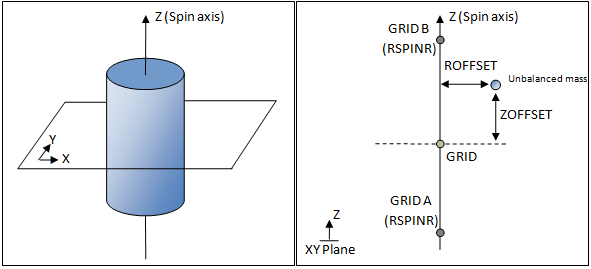
| 5. | The rotation of the unbalanced load occurs in the positive Z direction which is defined by GRIDA and GRIDB on the RSPINR bulk data entry. |
| 6. | The initial position of the unbalanced mass and the direction of its subsequent rotation are defined with respect to a cylindrical coordinate system. Its angular position is measured from the plane defined by both the Z-axis and the vector (X1, X2, and X3) with THETA=0.0 being the direction of the vector (X1, X2, and X3) itself. The rotation of the unbalanced load occurs in the positive Z direction. |
See Also: