HyperWorks Tools

Bushing Property File

Bushing Property File

Previous topic Next topic Expand/collapse all hidden text  

Bushing Property File

Previous topic Next topic JavaScript is required for expanding text JavaScript is required for the print function  

The Altair Bushing Model reads a property file that contains all of the information required for a bushing at run-time. This property file is known as the Bushing Property file or General Bushing System property file and uses the extension .gbs.

The following table shows the structure of the .gbs file:

Structure of the GBS File

[HEADER]

[UNITS]

[GLOBAL]

[DIRECTIONS]

[FRICTION]


[SPLINE_STIFFNESS_FX]

[CONSTANT_STIFFNESS_FX]

[CUBIC_STIFFNESS_FX]

[CONSTANT_DAMPING_FX]

[RUBBER_DAMPING_FX]

[HYDROMOUNT_DAMPING_FX]

[SPLINE_STIFFNESS_FY]

[CONSTANT_STIFFNESS_FY]

[CUBIC_STIFFNESS_FY]

[CONSTANT_DAMPING_FY]

[RUBBER_DAMPING_FY]

[HYDROMOUNT_DAMPING_FY]

[SPLINE_STIFFNESS_FZ]

[CONSTANT_STIFFNESS_FZ]

[CUBIC_STIFFNESS_FZ]

[CONSTANT_DAMPING_FZ]

[RUBBER_DAMPING_FZ]

[HYDROMOUNT_DAMPING_FZ]


[SPLINE_STIFFNESS_TX]

[CONSTANT_STIFFNESS_TX]

[CUBIC_STIFFNESS_TX]

[CONSTANT_DAMPING_TX]

[RUBBER_DAMPING_TX]

[HYDROMOUNT_DAMPING_TX]


[SPLINE_STIFFNESS_TY]

[CONSTANT_STIFFNESS_TY]

[CUBIC_STIFFNESS_TY]

[CONSTANT_DAMPING_TY]

[RUBBER_DAMPING_TY]

[HYDROMOUNT_DAMPING_TY]


[SPLINE_STIFFNESS_TZ]

[CONSTANT_STIFFNESS_TZ]

[CUBIC_STIFFNESS_TZ]

[CONSTANT_DAMPING_TZ]

[RUBBER_DAMPING_TZ]

[HYDROMOUNT_DAMPING_TZ]


The .gbs file uses the TeimOrbit format organized into the following blocks:

Block Type

Description

HEADER

Mandatory block specifying the file type, version, and format information for use by file readers.

UNITS

Mandatory block that specifies the unit system for parameter values in the property file. This block enables file readers to convert the parameter values in the property file to those used in the simulation.

GLOBAL

Mandatory block specifying whether or not to couple the X-, Y-, and Z-direction force computations and the X-, Y-, and Z-direction moment computations.

DIRECTIONS

Mandatory block that specifies the force formulations active for each force and moment direction.

PARAMETER

Parameter blocks for the active force methods for each direction.  For each force direction of interest the .gbs file contains six blocks. These are shown in brown in the figure below. In order to conserve space, the force blocks are shown in multiple columns, though in the file they are organized one below the other. Since six possible directions of interest exist, the .gbs file can contain up to 36 blocks of information containing the force data.

The string, FX, FY, FZ, TX, TY, or TZ, is appended to the block name to identify the direction, for example: [CONSTANT_STIFFNESS_FZ].   Force models selected in the ACTIVITY table must have a corresponding parameter block in the .gbs file. Parameter blocks are available for the following force methods:

FRICTION

Friction blocks support the parameters for the LuGre friction model—a model that supports both static and dynamic friction.


The following section provides a detailed definition for each block:


hmtoggle_plus1greyHeader Block

The header block contains metadata for use by file readers to identify the type, version and format of the file. This is a mandatory block.  The keywords that are used in this block are:

Parameter

Type

Description

FILE_TYPE

quoted_string

The only legal value is 'gbs'.

FILE_VERSION

quoted_string

The only legal value is '1'.

FILE_FORMAT

quoted_string

The only legal value is 'ASCII'.


The following is an example of a HEADER block:


$-----------------------------------------------------------------HEADER

[HEADER]

FILE_TYPE     = 'gbs'

FILE_VERSION  = '1'

FILE_FORMAT   = 'ASCII'


hmtoggle_plus1greyUnits Block

The units block specifies the unit system used for the values in the property file. This is a mandatory block. The units must be defined for length, time, force, mass, and angle.

The table below describes the valid choices for the Units block:

Parameter

Type

Description

LENGTH

quoted_string

Valid length units are:

mm
m
meter
cm
mile
foot
inch

ANGLE

quoted_string

Valid angle units are:

degree
radian

FORCE

quoted_string

Valid force units are:

newton
kg_force
knewton
pound_force
kpound_force
dyne
ounce_force

MASS

quoted_string

Valid mass units are:

kg
gram
pound_mass
kpound_mass
slug
ounce_mass

TIME

quoted_string

Valid time units are:

second
sec
millisecond
minute
hour


The following is an example of a Units block:

$--------------------------------------------------------------- UNITS

[UNITS]

LENGTH = 'mm'

ANGLE = 'degree'

FORCE = 'newton'

MASS = 'kg'

TIME = 'second'


hmtoggle_plus1greyGlobal Block

The Global block contains settings for coupling the X, Y, and Z direction force computations and the X, Y, Z direction moment computations. This block is mandatory.

Parameter

Type

Units

Description

EPSILON

Real

No-units

Unused at present. Ignore when reading file.

COUPLING

String

No-units

Valid choices are:

UNCOUPLED ->

X, Y, and Z forces computed independently.

CYLINDRICAL->

X and Y forces are coupled.

SPHERICAL->

X, Y, and Z forces are coupled.

The following is an example of a Global block:

$-------------------------------------------------------------- GLOBAL

[GLOBAL]

COUPLING = 'spherical'


hmtoggle_plus1greyDirections Block

The Directions block selects what force formulations the simulation model uses for each force and torque direction.  This is a mandatory block. The block contains a table where each row is a force method and each column a force or torque direction. To select or turn on a force formulation for a given force direction, enter 1 in the corresponding row and column. To turn off a force method for a given force direction, enter 0 (zero).

Parameter

Type

Units

Description

ACTIVITY

Sub-block

-

This sub-block is specified as (ACTIVITY)  

FORMULATION

String

-

Valid choices are:

'SPLINE_STIFFNESS'
'CUBIC_STIFFNESS'
'CONSTANT_STIFFNESS'

FX

Integer

-

Valid choices are:

0 – do not select
1 – select

FY

Integer

-

FZ

Integer

-

TX

Integer

-

TY

Integer

-

TZ

Integer

-

Some of the formulations are mutually exclusive and some of the formulations can be added in parallel.

Each force direction (one column in the matrix below) can contain only one stiffness model and one damping model.
HYDROMOUNT_DAMPING can be used for one translational direction ONLY. Because the software does not impose this limitation, understanding the impracticality of fitting more than one hydromount per attachment is important.
Where HYDROMOUNT_DAMPING is used (for FX, FY, FZ), the RUBBER_DAMPING for the same direction CANNOT be used.
CONSTANT_STIFFNESS, SPLINE_STIFFNESS and CUBIC_STIFFNESS are mutually exclusive.


In the following example, the stiffness models are shown in blue and damping models in green.

For FX: SPLINE_STIFFNESS and RUBBER_DAMPING are active.
For FY: CONSTANT_STIFFNESS and HYDROMOUNT_DAMPING are active.
For FZ: CONSTANT_STIFFNESS and CONSTANT_DAMPING are active.
For TX: CUBIC_STIFFNESS and CONSTANT_DAMPING are active.
For TY: CONSTANT_STIFFNESS and CONSTANT_DAMPING are active.
For TZ: SPLINE_STIFFNESS and RUBBER_DAMPING are active.


$$---------------------------------------------------------- DIRECTIONS

[DIRECTIONS]

(ACTIVITY)

{   formulation       FX  FY  FZ   TX  TY  TZ  }

'SPLINE_STIFFNESS'    1   0   0    0   0   1

'CONSTANT_STIFFNESS'  0   1   1    0   1   0

'CUBIC_STIFFNESS'     0   0   0    1   0   0

'CONSTANT_DAMPING'    0   0   1    1   1   0

'RUBBER_DAMPING'      1   0   0    0   0   1

'HYDROMOUNT_DAMPING'  0   1   0    0   0   0


The net force output for any direction is the sum of the forces due to the active force formulations in that direction.


hmtoggle_plus1greyParameter Block

Parameter blocks include one block for each available force method as follows:

Spline stiffness blocks store the static stiffness properties of a bushing. The data is stored in a table of monotonically increasing deflections versus forces. If the direction block selects the spline stiffness formulation for a given direction, for example FZ, then the property file should contain a corresponding spline stiffness block for that direction, such as [SPLINE_STIFFNESS_FZ].

The following table shows the parameters stored in spline stiffness blocks.

Abbreviations are [A] = angle dimension,  [F] = force, [L] = length.

Parameter

Type

Dimension FX, FY, FZ

Dimension TX, TY, TZ

Displacement

real

[L]

[A]

Force

real

[F]

[F][L]

When the property file is read the deflection and force values are converted from the units of the property file to the units of the solver model.

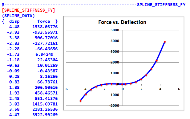
The example below shows a typical spline block in the .gbs file for the FY direction. The plot next to the data is not a part of the .gbs file, but is included here to show you the shape of the curve.
 

spline_stiffness


Cubic Stiffness blocks store a set of coefficients that determine two cubic polynomials defining a force verses deflection curve. If the Direction block selects the cubic stiffness formulation for TY direction, then the property file, for example, must contain a [CUBIC_STIFFNESS_TY] block.

The following table describes the parameters stored in a Cubic Stiffness block. Abbreviations are: [F] = force, [L] = length.

Parameter

Type

Dimension FX, FY, FZ

Dimension TX, TY, TZ

EN

real

[L]

Angle

ENS

real

[F][L-1]

[F][L] /Angle

RN

real

[L]

Angle

RNF

real

[F]

[F][L]

OS

real

[F][L-1]

[F][L] /Angle

OF

real

[F]

[F][L]

O

real

[L]

Angle

RP

real

[L]

Angle

RPF

real

[F]

[F][L]

EP

real

[L]

Angle

EPS

real

[F][L-1]

[F][L] /Angle

In a property file, a cubic stiffness block has this form:
 

[CUBIC_STIFFNESS_TY]

EN  =  -0.20

ENS =  200000.0

RN  = -0.10

RNF = -30000.0

O   =  0.0

OF  =  0.0

OS  =  20000.0

RP  =  0.10

RPF =  30000.0

EP  =  0.20

EPS =  200000.0


Constant Stiffness blocks store the translational or rotational stiffness for a given direction.

The following table describes the parameters stored in a Constant Stiffness block. Abbreviations are: [A] = angle dimension,  [F] = force, [L] = length.

Parameter

Type

Units FX, FY, FZ

Units TX, TY, TZ

K

real

[F][L-1]

[F][L][A-1]

If the direction block selects the constant stiffness formulation for the FZ direction, then the property file, for example, must contain a [CONSTANT_STIFFNESS_FZ] block.  The form of the block is:
 

[CONSTANT_STIFFNESS_FZ]

K = 6000.0

The dimension for stiffness for translational directions is [F][L-1] and for rotational directions [F][L]. When read from the property file, the stiffness is converted from the units defined in the property file to the solver model units.


Constant Damping blocks store the damping coefficient for a given direction.

The following table describes the parameters stored in a Constant Damping block. Abbreviations are: [A] = angle dimension,  [F] = force, [L] = length, [T] = time.

Parameter

Type

Units FX, FY, FZ

Units TX, TY, TZ

C

real

[F][T][L-1]

[F][T][L][A-1]

If the direction block selects the constant damping formulation for the FX direction, then the property file, for example, must contain a [CONSTANT_DAMPING_FX] block.  The form of the block is:
 

[CONSTANT_DAMPING_FX]

C = 600.0

The dimension for the damping coefficient for translational directions is [F][T][L-1] and for rotational directions [F][T][L].  When read from the property file, the damping coefficient is converted from the units defined in the property file to the solver model units.


The following is true:

For each force or torque direction using the Rubber-Damping formulation as specified in the [DIRECTION] block, the property file must contain a corresponding RUBBER_DAMPING block giving the thirteen (13) rubber damping parameters. The block name is a concatenation of RUBBER_BUSHING_ and the force or moment direction.  For example, if the direction is TX, then the block name is [RUBBER_BUSHING_TX].
The data block contains a scalar value that determines the number of preload sub-blocks: NPRELOADS = X
For each preload there must be a corresponding data sub-block defined as: (PRELOAD_N) where N is a number from 1 to M with M being the total number of preloads.
Each Rubber Bushing block in the property file must contain all thirteen (13) rubber damping parameters. The name, type and dimension for each parameter is listed in the table below.
An optional 14th parameter, RMIN, is available to define the minimum cut-off time constant that the simulation model should use. If the value of the cut-off time constant, R, which is computed by the fitting tool, is less than RMIN, then RMIN is used. Large values of RMIN allow more frequencies to pass through the filtering mechanism. Also note that the frequency response of the bushing deviates from the experimental measurements that were made.
When not specified, RMIN defaults to 0.0, a value that guarantees for RMIN not to be used.


The following table describes the parameters stored in a Constant Rubber Damping block. Abbreviations are: [A] = angle dimension,  [F] = force, [L] = length, [T] = time.

Parameter

Type

Dimension FX, FY, FZ

Dimension TX, TY, TZ

R

real

[T-1]

[T-1]

K0

real

[F][L-1]

[F][L] /Angle

K1

real

[F][L-1]

[F][L] /Angle

K2

real

[F][L-1]

[F][L] /Angle

C0

real

[F][T][L-1]

[F][T][L] /Angle

C1

real

[F][T][L-1]

[F][T][L] /Angle

C2

real

[F][T][L-1]

[F][T][L] /Angle

P0

real

No-Units

[F][L] /Angle

P1

real

[L-P2]

Angle[L-P2]

P2

real

No-Units

No-Units

Q0

real

No-Units

No-Units

Q1

real

[L-Q2][TQ2]

[Angle-Q2][TQ2]

Q2

real

No-Units

No-Units

optional

RMIN

real

[T-1]

[T-1]

The following is an example of the RUBBER_DAMPING block for the X direction:
 

$---------------------------------------------------------------

[RUBBER_DAMPING_FX]

SPD_FILE_NAME = 'C:\Users\rajivr\Desktop\input_50289_fx.spd'

NPRELOADS  = 1

(PRELOAD_1)

PRELOAD     =  0.0000000000000000E+000

R           =  3.7304938466506937E-001

C0          =  3.9148912713636901E+002

K0          =  1.4925221392833666E+003

C1          =  3.5544374604832620E+002

K1          =  1.2799236592247264E+004

C2          =  7.3796362578278907E-001

K2          =  1.0076285596442904E-001

P0          =  3.0189673042568872E+000

P1          = -2.3806569863314331E+000

P2          =  2.5826224628819706E-002

Q0          =  5.7885657452072947E-001

Q1          = -9.8019268585634856E-001

Q2          =  2.0000000000000000E+000


This block stores a set of coefficients for the hydromount formulation.  The block name is a concatenation of HYDROMOUNT_DAMPING_ and the force or moment direction. For instance, if the direction block selects the hydromount formulation for the FZ direction, then the property file should contain a [HYDROMOUNT_DAMPING_FZ] block.

The data block contains a scalar value that determines the number of preload sub-blocks. For each preload there must be a corresponding data sub-block defined as: (PRELOAD_N) where N is a number from 1 to M with M being the total number of preloads.

Each Hydromount Damping block in the property file must contain all twenty-two (22) hydromount damping parameters.

The following table shows the names, type and dimension of the parameters. Abbreviations are:  [A] = angle dimension,  [F] = force, [L] = length, [T] = time.

Parameters associated with the rubber are shown in light green cells.
Parameters associated with the fluid model are shown in light pink cells.
Parameters associated with transition from rubber to full hydromount are shown in white cells.


Parameter Name

Type

Units FX, FY, FZ

R

real

[T-1]

K0

real

[F][L-1]

K1

real

[F][L-1]

K2

real

[F][L-1]

C0

real

[F][T][L-1]

C1

real

[F][T][L-1]

C2

real

[F][T][L-1]

P0

real

No-Units

P1

real

[L-P2]

P2

real

No-Units

Q0

real

No-Units

Q1

real

[L-Q2][TQ2]

Q2

real

No-Units

MN

real

[M]

KH

real

[F][L-1]

CH1

real

[F][T][L-1]

CH2

real

[F][T][L-1]

JO

real

No-Units

J1

real

[L-P2]

J2

real

No-Units

L0

real

No-Units

L1

real

[L-Q2][TQ2]

L2

real

No-Units

XR

real

[L]

XH

real

[L]

In a property file, a Hydromount Damping block has this form:
 

[HYDROMOUNT_DAMPING_FZ]

SPD_FILE_NAME = 'C:\Users\rajivr\Desktop\input_50289_fz.spd'

NPRELOADS = 1


(PRELOAD_1)

PRELOAD = 0.0

R       = 0.001

C0      = 308.74

K0      = 275.345

C1      = 111.554

K1      = 1659.511332

C2      = 0.266419

K2      = 4.01626

P0      = 1.0

P1      = 0.0

P2      = 1.0

Q0      = 1.0

Q1      = 0.0

Q2      = 1.0


Mh      = 0.01

Kh      = 90.0

Ch1     = 0.10

Ch2     = 0.50

J0      = 1.0

J1      = 0.0

J2      = 1.0

L0      = 1.0

L1      = 0.0

L2      = 1.0


XR      = -1.0

XH      = 0.0


hmtoggle_plus1greyFriction Block

Friction parameters for the LuGre model are defined in the Friction block as shown in the following table:

Parameter Name

Dimension

Mu_Static

Specifies the static friction coefficient

in the connector.

MU_STATIC > 0.

This is a mandatory parameter and it must be specified.

Recommended Value: 0.5

Mu_Dynamic

Specifies the dynamic friction coefficient

in the connector.

0 ≤ MU_DYNAMIC ≤ MU_STATIC.

This is a mandatory parameter and it must be specified.

Recommended Value: 0.3

Analysis_Modes

Specifies the analysis modes for which the frictional effect is on. The choices are the strings:

‘STATICS_AND_DYNAMICS’
‘DYNAMICS_ONLY’

This is an optional parameter that defaults to ‘DYNAMICS_ONLY’. Both static and dynamic frictions are considered.

Recommended Value: ‘STATICS_AND_DYNAMICS’.

Effect

Specifies the types of friction models to support. Available options are:

‘STICTION’
‘SLIDING’

This is a mandatory parameter and it must be specified.

Recommended Value: ‘SLIDING’.

Transition_Velocity

The absolute velocity at which the friction transitions from dynamic friction to static friction. TRANSITION_VELOCITY > 0.

This is a mandatory parameter and it must be specified.

Recommended Value: 0.1 mm/second.

Bristle_Stiffness

Specifies the bristle stiffness in the LuGre model. Usually represented as .

BRISTLE_STIFFNESS > 0.

This is a mandatory parameter and it must be specified.

Recommended Value: 100.0/mm.

Bristle_Damping

Defines the damping coefficient for the pre-displacement (or stiction) regime. Its main role is to damp out bristle vibrations in the pre-displacement regime. Usually represented as .

BRISTLE_DAMPING ≥ 0.

This is a mandatory parameter and it must be specified.

Recommended Value: 0.316 second/mm.

Slip_Damping

Specifies the coefficient for the viscous damping force that occurs when relative sliding actually begins.  Usually represented as .

SLIP_DAMPING ≥ 0.

This is a mandatory parameter and it must be specified.

Recommended Value: 0.0004 second/mm.

Torque_From_Preload

Specifies the preload friction torque in the Spherical Connectors.

TORQUE_FROM_PRELOAD ≥ 0.

This is a mandatory parameter and it must be specified.

Recommended Value: Not available.

Ball_Radius

Specifies the radius of the spherical connector.

BALL_RADIUS > 0.

This is a mandatory parameter and it must be specified.

Recommended Value: Not available.


The following table describes the type and dimension for the various input parameters. Abbreviations are: [F] = force, [L] = length, [T] = time.

Parameter Name

Type

Dimension

Mu_Static

real

No-Units

Mu_Dynamic

real

No-Units

Analysis_Modes

string

-

Effect

string

-

Transition_Velocity

real

[L][T-1]

Bristle_Stiffness

real

[L-1]

Bristle_Damping

real

[T][L-1]

Slip_Damping

real

[T][L-1]

Torque_From_Preload

real

[F][L]

Ball_Radius

real

[L]


The example below shows the specification of a LuGre Friction block in the .gbs file:

$---------------------------------------------------------------

[LUGRE_FRICTION]

MU_STATIC           = 0.0

MU_DYNAMIC          = 0.0

ANALYSIS_MODES      = 'STATICS_AND_DYNAMICS'

EFFECT              = 'SLIDING'

USE_FORCE           = 'YES'

TRANSITION_VELOCITY = 0.1000

BRISTLE_STIFFNESS   = 0.0100

BRISTLE_DAMPING     = 0.31625

SLIP_DAMPING        = 0.0008

TORQUE_FROM_PRELOAD = 526.882

BALL_RADIUS         = 10.0