Connectivity |

|

|

|

|
|
Connectivity |

|

|

|

|
This section describes how you attach a bushing to a model.
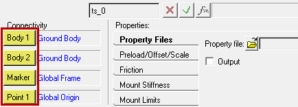
On the AutoBushFD panel, the Connectivity fields include a set of four yellow Collector buttons:

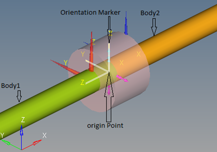
You use the Collector buttons to select the two bodies the bushing connects, the Marker that orients the bushing, and the Point that locates the bushing.
The figure below illustrates the Bodies, Marker and Point required to attach a bushing to a model:

The following table describes the Collectors for Connectivity:
Collector |
Description |
Body 1 |
Click the collector button to select a body from the graphics window, or double-click to select a body from the browser dialog. |
Body 2 |
Click the collector button to select a body from the graphics window, or double-click to select a body from the browser dialog. |
Marker |
Click the collector button to select a marker from the graphics window, or double-click to select a marker from the browser dialog. Markers for the X, Y, and Z axes define the bushing’s X, Y, and Z axes. |
Point 1 |
Click the collector button to select a point from the graphics window or double-click to select a point from the browser dialog. The point’s location defines the bushing’s location. |