|
»Click here to display Table of Contents«
|

Modifying Bushings |

|

|

|

|
|
Modifying Bushings |
|
|
|

|
|
»Click here to display Table of Contents«
|
Modifying Bushings |
|
|
|
|
|
Modifying Bushings |
|
|
|
|
This topic shows you how to modify and make specifications for bushings using the Connectivity, Symmetry and Properties options in the MotionView User Interface.
Option |
Description |
||||||||||
The pane on the UI where you define how your bushing system attaches to your model. |
|||||||||||
The pane on the UI that includes five sub tabs from which you enter bushing properties:
|
|||||||||||
The field on the UI where you define a symmetric or asymmetric bushing system. Symmetry, if used, is assumed to be about the global X-Z plane. |
To define a single, frequency-dependent bushing using the Connectivity, Symmetry and Properties options, do the following.
| 1. | From the Model browser in MotionView, select the entity AutoBushFD that you created in the topic, Adding the Altair Bushing Model: |
| 2. | The following window appears at the bottom of your screen: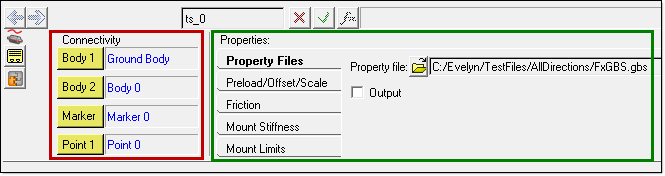 |
The window includes a Connectivity pane, shown outlined in red, and a Properties pane, shown outlined in green. For more details about the options in each pane, see the links at the beginning of this section.