|
»Click here to display Table of Contents«
|

AutoBush |

|

|

|

|
|
AutoBush |
|
|
|

|
|
»Click here to display Table of Contents«
|
AutoBush |
|
|
|
|
|
AutoBush |
|
|
|
|
The Autobush is a bushing model that is designed to easily simulate bushings used in ground vehicles. The Autobush entity reads bushing stiffness (force-displacement) and damping (force-velocity) data from a file written in the TeimOrbit format.
Some advantages of the Autobush element include the following:
| • | Forces-deflection properties are stored in one ASCII format file, called the property file. |
| • | Multiple bushings may reference the same property file. |
| • | The property file format is compatible with other MBD codes, such as SIMPACK and ADAMS. |
| • | Bushing Coupling is supported as a user selected choice. |
The Autobush uses a Force_field XML statement in the MotionSolve deck, along with a subroutine to calculate the bushing forces and moments. The bushing property file is read by MotionSolve at the beginning of the simulation. MotionSolve uses Akima’s method to interpolate the force-deflection curves stored in the property file. For deflections outside the range in the property file, MotionSolve linearly extrapolates forces and/or moments.
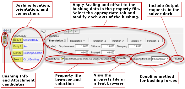
The MotionView graphical user interface is shown below. The function of each section of the interface is also described in the image below:
A bushing Graphic appears when an Autobush is added using the interface. The graphic includes a cylinder, and two large X-Y local coordinate frame indicators.
The height direction of the cylinder is along the bushing local Z axis. The radial directions of the cylinder are along the bushing Local X and Y coordinate frames. The red axis indicator is aligned with the bushing local X axis, and the blue axis indicator is along the bushing local Y axis. Two different indicators are on shown for the autobush. The red/blue indicator is displayed at +20 mm along the bushing local Z axis, and the blue/blue axis indicator is shown at -20 mm along the bushing local Z axis.
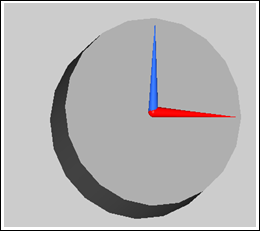
Autobush Bushing Graphic
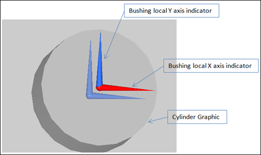
Autobush Bushing Graphic-Cylinder graphic shown as transparent
The connections define the two connecting bodies, the point where the forces act, and the marker that defines the bushing orientation. Bodies, Markers, and Points can be selected either graphically or through the Project Browser.
Connectivity |
Description |
|---|---|
Body 1 |
Select the first body the bushing connects. The I marker of the Force_field statement in the solver deck lies on Body 1, is located at Point1, and has the orientation of Marker. |
Body 2 |
Select the second body the bushing connects. The J marker of the Force_field statement in the solver deck lies on Body, is located at Point 1, and has the orientation of Marker. |
Marker |
Select a marker to orient the bushing in space. All three axes of the bushing are along the axes of the respective axes of the Marker (X-X,Y-Y,Z-Z). |
Point 1 |
Select a point to locate the bushing. The point defines the location where the bushing forces act. The I marker and the J (floating) marker of the Force_field statement are at Point 1. |
The property file section is a file browser and selection utility used to identify the bushing property file. The file path is written to the solver deck and the file is read when the solver executes. The property file is written in the TeimOrbit format. A sample file is shown in the TeimOrbit section (below).
View file brings up the bushing property file in a text file browser. The file can be read, however it cannot be edited or saved.
The coupling method determines how the displacements in the bushing are computed. The three methods are described in the table below:
Note - The coupling method does not matter for a linear rate bushing.
Method |
Description |
|---|---|
Rectangular |
The displacement on each axis of the bushing is computed independently. |
Cylindrical |
Couple the X and Y displacements (translational and rotational). The radial deflection (r) is given by: r = sqrt( x^2 + y^2 ) Fx = x/r*Gx( sign(x)*r ) Fy = y/r*Gy( sign(y)*r ) Where Gx and Gy are the force-deflection curves in the property file. The moments about the X and Y bushing axes are treated similarly. |
Spherical |
Couple the X, Y, and Z direction displacements (translational and rotational). The radial deflection (r) is given by: r = sqrt( x^2 + y^2 + z^2 ) Fx = x/r*Gx( sign(x)*r ) Fy = y/z*Gy( sign(y)*r ) Fz = z/r*Gz( sign(z)*r ) |
Checking the Output box will write requests into the solver deck that request the force in the bushing, the displacement across the bushing, and the relative velocity across the bushing.
When plotting using the .abf file, the requests appear under the REQSUB type. The Bushing label (“AutoBush 0” in this example) is added to the request type (“Force-Bushing”,”Displacement Bushing”, etc.) and put in the Request Description to help you understand requests when plotting them. The Bushing Label can be changed in the MotionView graphical user interface to provide a meaningful description of the bushing.
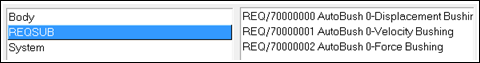
Figure-Autobush requests using the .abf file
When plotting data using the .plt file the requests appear under the User Defined request type as shown below:
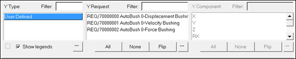
Figure-Autobush requests using the .plt file
Data is reported in the following columns in the .abf and .plt files:
Displacement Results |
X Dis |
Y Dis |
Z Dis |
Dis |
X Rot |
Y Rot |
Z Rot |
Rot |
|---|---|---|---|---|---|---|---|---|
.abf file |
Result(2) |
Result(3) |
Result(4) |
Not Reported |
Result(6) |
Result(7) |
Result(8) |
Not Reported |
.plt file |
X |
Y |
Z |
MAG |
RX |
RY |
RZ |
RMAG |
Velocity Results |
X Vel |
Y Vel |
Z Vel |
Vel |
X Rot Vel |
Y Rot Vel |
Z Rot Vel |
Rot Vel Mag |
|---|---|---|---|---|---|---|---|---|
.abf file |
Result(2) |
Result(3) |
Result(4) |
Not Reported |
Result(6) |
Result(7) |
Result(8) |
Not reported |
.plt file |
X |
Y |
Z |
MAG |
RX |
RY |
RZ |
RMAG |
Force |
X For |
Y For |
Z For |
For |
X Mom |
Y Mom |
Z Mom |
Mom |
|---|---|---|---|---|---|---|---|---|
.abf file |
Result(2) |
Result(3) |
Result(4) |
Result(1) |
Result(6) |
Result(7) |
Result(8) |
Result (5) |
.plt file |
X |
Y |
Z |
MAG |
RX |
RY |
RZ |
RMAG |
Displacements, Velocities, and Forces are reported in the units used in the MotionView model.
A sample TeimOrbit format text file is shown below. The blocks have the following meaning:
HEADER -The header block describes the format of the file, if it was written from a pre-processor.
UNITS - To describe the data in this file.
DAMPING - Damping in the bushing. Linear damping is supported in this bushing model and is shown in the file below.
FX_CURVE, FYCURVE, etc. - Displacement vs Force data for the degree of freedom identified in the block header. Enter the data in ascending order.
$-------------------------------------------------------------------HEADER
[HEADER]
FILE_TYPE = 'bus'
FILE_VERSION = 4.0
FILE_FORMAT = 'ASCII'
$------------------------------------------------------------------UNITS
[UNITS]
LENGTH = 'mm'
ANGLE = 'degrees'
FORCE = 'newton'
MASS = 'kg'
TIME = 'second'
$-----------------------------------------------------------------DAMPING
[DAMPING]
FX_DAMPING = 0.5
FY_DAMPING = 0.5
FZ_DAMPING = 0.5
TX_DAMPING = 0.5
TY_DAMPING = 0.5
TZ_DAMPING = 0.5
$----------------------------------------------------------------FX_CURVE
[FX_CURVE]
{ x fx}
-10.0 -45000.0
-8.0 -36000.0
-6.0 -27000.0
-4.0 -18000.0
-2.0 -9000.0
0.0 0.0
2.0 9000.0
4.0 18000.0
6.0 27000.0
8.0 36000.0
10.0 45000.0
$----------------------------------------------------------------FY_CURVE
[FY_CURVE]
{ y fy}
-10.0 -45000.0
-8.0 -36000.0
-6.0 -27000.0
-4.0 -18000.0
-2.0 -9000.0
0.0 0.0
2.0 9000.0
4.0 18000.0
6.0 27000.0
8.0 36000.0
10.0 45000.0
$----------------------------------------------------------------FZ_CURVE
[FZ_CURVE]
{ z fz}
-10.0 -45000.0
-8.0 -36000.0
-6.0 -27000.0
-4.0 -18000.0
-2.0 -9000.0
0.0 0.0
2.0 9000.0
4.0 18000.0
6.0 27000.0
8.0 36000.0
10.0 45000.0
$----------------------------------------------------------------TX_CURVE
[TX_CURVE]
{ ax tx}
-45.0 -2025000.0
-36.0 -1620000.0
-27.0 -1215000.0
-18.0 -810000.0
-9.0 -405000.0
0.0 0.0
9.0 405000.0
18.0 810000.0
27.0 1215000.0
36.0 1620000.0
45.0 2025000.0
$----------------------------------------------------------------TY_CURVE
[TY_CURVE]
{ ay ty}
-45.0 -2025000.0
-36.0 -1620000.0
-27.0 -1215000.0
-18.0 -810000.0
-9.0 -405000.0
0.0 0.0
9.0 405000.0
18.0 810000.0
27.0 1215000.0
36.0 1620000.0
45.0 2025000.0
$----------------------------------------------------------------TZ_CURVE
[TZ_CURVE]
{ az tz}
-45.0 -2025000.0
-36.0 -1620000.0
-27.0 -1215000.0
-18.0 -810000.0
-9.0 -405000.0
0.0 0.0
9.0 405000.0
18.0 810000.0
27.0 1215000.0
36.0 1620000.0
45.0 2025000.0