AutoMFTire |

|

|

|

|
|
AutoMFTire |

|

|

|

|
The (Magic Formula) MF-Tire models the longitudinal dynamics of a vehicle, keeping the axle, wheel and tire in contact with a road represented by the Magic Formula and optional deformation compliance. Tire models apply forces and moments on wheel body so as to simulate a real tire forces and moments that tires apply on the vehicle.
The tire models MF-Tire and MF-Swift (Short Wavelength Intermediate Frequency Tire) can be used in vehicle dynamics simulations in all popular simulation packages to efficiently, and accurately, represent tire behavior for applications ranging from steady-state to complex high frequency dynamics.
Altair MotionView and MotionSolve support multiple tire models through the TNO defined interface.
With MF-Tire, you can simulate steady-state and transient behavior, making it a suitable tire model for:
| • | Vehicle handling |
| • | Control prototyping |
| • | Rollover analysis |
With MF-Swift, you can simulate tire dynamic behavior up to about 100 Hz, which is particularly useful for:
| • | Vehicle comfort |
| • | Durability |
| • | Vehicle control prototyping, or |
| • | Vibration analysis |
For this tire interface, the tire parameters and properties are set by a Tire Property File with the extension (.tir) while the road interface is described by a Road Property File with the extension (.rdf). Both of these property files are in the TeimOrbit file format. Example property files are provided in the MotionView installation at:
$(ALTAIR_HOME) \hw\mdl\autoentities\properties\Tires < tire property file with .tir extension>
$(ALTAIR_HOME) \hw\mdl\autoentities\properties\Tires < road property file with .rdf extension>
In addition to this, physical properties of the tire such as the unloaded radius, aspect ratio, width, mass, and moment of inertia’s need to be explicitly specified.
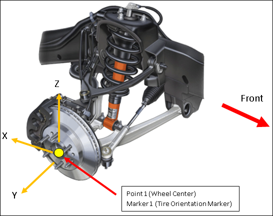
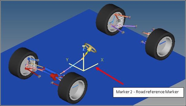
Select the Body to which the tire is to be attached, select the point that represents the wheel center, and select the two markers that set the orientation of the tire.
Connection |
Significance |
|---|---|
Body 1 |
The wheel body on which the tire forces act. |
Point 1 |
The point corresponding to the wheel center. |
Marker 1 |
The wheel reference marker which determines the direction in which the tire forces act. |
Marker 2 |
The road reference marker, is the marker with respect to which the road is positioned and oriented for the simulation |


The Auto MF-Tire Auto Entity can be added to a full vehicle model as a Single entity or as a Pair. The Pair entity, like other MotionView Pair entities, establishes two symmetric (left and right) Tire models about the X axis.

An additional option determines if the symmetry should be mapped from left to right or right to left. Symmetry can be disabled for Auto MF-Tire Pairs.
Information about the tire physical tire properties such as unloaded radius, aspect ratio, width, mass, and moment of inertia need to be provided correctly. These are specified in the panel in the section highlighted below:

Parameter |
Description |
Units [Model Units] |
|---|---|---|
Unloaded radius |
Distance between the WC and the contact point of tire in unloaded conditions. |
Length |
Aspect ratio |
Tire Sidewall profile aspect ratio. Describes the sidewall height as a percentage of the tire section width. |
% |
Width |
Section width of the tire. |
Length |
Tire mass |
Mass of the tire. |
Mass |
Ixx,Iyy,Izz |
Moment of Inertia of the tire (y-axis out of plane of tire). |
Mass * Length2 |
The TNO interface implements two tire models:
| • | SWIFT TIRE – TNO |
| • | MF TIRE – TNO |
The parameter PROPERTY_FILE_FORMAT in the MODEL section of the tire property file determines tire model used. The User is expected to choose a compatible road model with the tire model chosen via the property file.
Sample Property Files:
[HEADER] FILE_TYPE ='tir' FILE_VERSION =3.0 FILE_FORMAT ='ASCII' ! ! FILE_NAME : TNO_car205_60R15.tir ! TIRE_VERSION : MF-Tyre/MF-Swift 6.1 ! MF-TOOL TEMPLATE : TNO_mfswift61 $Revision: 1.11 $ ! ! Copyright TNO 2010 ! $----------------------------------------------------------------units [UNITS] LENGTH ='meter' FORCE ='newton' ANGLE ='radians' MASS ='kg' TIME ='second' $----------------------------------------------------------------model [MODEL] FITTYP = 61 $Magic Formula Version number TYRESIDE ='Left' LONGVL = 16.7 $Nominal speed VXLOW = 1 $Lower boundary of slip calculation ROAD_INCREMENT = 0.01 $Increment in road sampling ROAD_DIRECTION = 1 $Direction of travelled distance ! PROPERTY_FILE_FORMAT = 'SWIFT-TYRE' FUNCTION_NAME = 'tnodelft::DTYRE' ROAD_SOURCE = 'TNO' USER_SUB_ID = 815 N_TIRE_STATES = 4 USE_MODE = 114 $Tyre use mode switch (ADAMS only) HMAX_LOCAL = 2.5E-4 $Local integration time step (ADAMS only) TIME_SWITCH_INTEG = 0.1 $Time when local integrator is activated (ADAMS only) $-----------------------------------------------------------dimensions [DIMENSION] UNLOADED_RADIUS = 0.3135 $Free tyre radius WIDTH = 0.205 $Nominal section width of the tyre RIM_RADIUS = 0.1905 $Nominal rim radius RIM_WIDTH = 0.152 $Rim width ASPECT_RATIO = 0.6 $Nominal aspect ratio $-------------------------------------------------operating conditions [OPERATING_CONDITIONS] INFLPRES = 220000 $Tyre inflation pressure NOMPRES = 220000 $Nominal tyre inflation pressure
(Truncated) |
$---------------------------------------------------------------------HEADER [HEADER] FILE_TYPE = 'rdf' FILE_VERSION = 5.00 FILE_FORMAT = 'ASCII' ! ! road data file for TNO_flat_road ! $--------------------------------------------------------------------------units [UNITS] LENGTH = 'meter' FORCE = 'newton' ANGLE = 'radians' MASS = 'kg' TIME = 'sec' $---------------------------------------------------------------------definition [MODEL] PROPERTY_FILE_FORMAT = 'USER' FUNCTION_NAME = 'mssticsub::ROAD' METHOD = '2D' ROAD_TYPE = 'flat' $---------------------------------------------------------------------parameters [PARAMETERS] MU = 1.0 $ peak friction scaling coefficient OFFSET = 0 $ vertical offset of the ground wrt inertial frame |
The Auto MF-Tire entity generates some standard output requests into the solver deck. These requests track the tire kinematics and the tire forces generated by the tire model.
Label |
Description |
Units |
|---|---|---|
Radius OmegaActual OmegaFree |
X – Deformed radius of the Tire. |
Length |
LonSlip LatSlip IncAngle |
X – Longitudinal Slip of the tire. In the ISO axis system. |
% rad rad |
Tire CP Forces |
Tire force and moments with reference to the ISO- Axis system at the tire contact patch. |
Force & |
Tire CP Forces |
Tire force and moments with reference to the SAE- Axis system at the tire contact patch. |
Force & |
LonSlip LatSlip IncAngle |
X – Longitudinal Slip of the tire. In the SAE axis system. |
[No Units] Deg Deg |
Tire Hub Forces |
Tire force and moments with reference to the ISO axis system at the wheel center. |
Force & |
Contact Patch Location |
X,Y,Z of the Contact Patch Location. |
Length |
Hub Velocity |
The translation and rotational velocities of the hub. |
Length / time |