AutoCDTire |

|

|

|

|
|
AutoCDTire |

|

|

|

|
The tire models describe the interface between the wheel and the road. Tire models apply forces and moments on wheel body so as to simulate a real tire forces and moments that tires apply on the vehicle.
Altair MotionView and MotionSolve support multiple tire models. One of the models supported on the windows platform is CD-Tire (Fraunhofer LBF). The CD-Tire is implemented via the Auto Entity: AutoTireCD.
The CD-Tire model is defined by a set of property files that describe the tire model parameters and the road model parameters. User defined road models are also supported with what is run with the model:
$(ALTAIR_HOME) \hw\mdl\autoentities\properties\Tires < tire property file with .tir extension>
$(ALTAIR_HOME) \hw\mdl\autoentities\properties\Tires < road property file with .rdf extension>
In addition to this, physical properties of the tire such as the unloaded radius, aspect ratio, width, mass, and moment of inertia’s need to be explicitly specified.
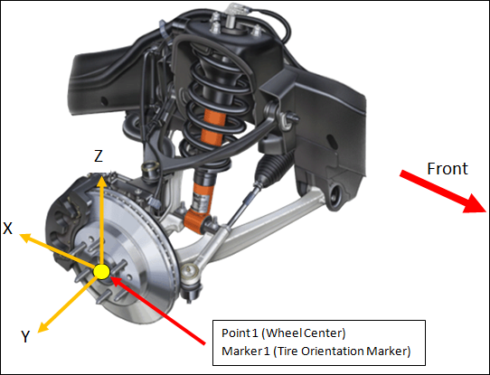
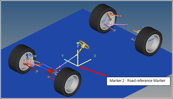
One Body, one Point, and two Marker connections need to be made to define the tire interface:
Connection |
Significance |
|---|---|
Body 1 |
The wheel body on which the tire forces act. |
Point 1 |
The point corresponding to the wheel center. |
Marker 1 |
The wheel reference marker which determines the direction in which the tire forces act. |
Marker 2 |
The road reference marker, is the marker with respect to which the road is positioned and oriented for the simulation. |


The AutoTireCD Auto Entity can be added to a full vehicle model as a Single entity or as a Pair. The Pair entity, like other MotionView Pair entities, establishes two symmetric (left and right) Tire models about the X axis. An additional option determines if the symmetry should be mapped from left to right or right to left. Symmetry can be disabled for AutoTireCD Pairs.

CD-Tire Version 3.0 is supported in this release. This release also supports various tire and road models as described below:
| • | CDTire 20-Rigid ring |
| • | CDTire 30-Flexible Ring |
| • | CDTire 40-3D Tire |
| • | CD2030- Adaptive tire |
| • | CD2040-Adaptive tire |
The tire models, their use, and the underlying assumptions behind them are described in the CDTire Users Manual provided by Fraunhofer LBF.
Road Surface
The complete Road Surface library is supported in this release, as described in the CD Tire manual. This includes the following road surface descriptions:
| • | Model 1000-Parametric road surface description |
| • | Model 1002-Rolling Drum Model |
| • | Model 1100-User defined |
| • | Model 2000-Parametric and digitized road surface |
Information about the physical tire properties such as mass, inertia, and dimensions need to be provided in the Geometry-Inertias Tab.

Parameter |
Description |
Units [Model Units] |
Unloaded radius |
Distance between the WC and the contact point of tire in unloaded conditions. |
Length |
Aspect ratio |
Tire Sidewall profile aspect ratio. Describes the sidewall height as a percentage of the tire section width. |
% |
Width |
Section width of the tire. |
Length |
Tire mass |
Mass of the tire. |
Mass |
Ixx,Iyy,Izz |
Moment of Inertia of the tire (y-axis out of plane of tire). |
Mass * Length2 |

The following files are required to specify the properties of the CD-Tire model:
This file contains the parameters used by CD-Tire to describe the tire model. The file format is defined by CD-Tire. The file name convention is described in the CD-Tire User Manual and is of the form <path> <name> <model> <type>. The naming convention must be followed strictly. The naming convention is described in the CD-Tire manual. Example: TIRE PARAMETER FOR CDTIRE 40 DIMENSION 195/65 R 15
NMP [1] NSP [1] NSEN [1] NFMIN [1] NFMAX [1] 200 3 5 1 100
RFEL [mm] BFEL [mm] MGRT [Ns^2/mm] 200.0 140.0 7.62E-3
RGRT [mm] BGRT [mm] 307.0 307.0 307.0 307.0 -70.0 -23.3 23.3 70.0
BETF [grad] RHOF [1/mm] 21.0 0.05
EFS [N] EFC [N] EIY [Nmm^2] EIX [Nmm^2] 1.35E6 1.51E6 2.65E6 1.37E9
FTX [Hz] FTY [Hz] FRY [Hz] 89.5 45.7 65.4
DTX [1] DTY [1] DRY [1] 0.05 0.05 0.05
KSRED [1] RADIAL_FREE [1] RADIAL_SPRING [1] 1.1 0.75 10.0
PREF [N/mm^2] PIN [N/mm^2] 2.2E-1 2.1E-1
EG [N/mm^2] KM [1] CREV [1] BL [N/mm^2] 134.4 0.9 1 44.8
HL [mm] 10.0 10.0 10.0 10.0
NGLT [1] 3
MGLT [1] VGLT [mm/s] 1.2 1.2 1.0 0.0 1.0E3 10.0E3
NRWB [1] 3
RWB [1] OMRW [rad/s] 0.0 0.0193 0.0193 0.0 0.3 1.0E4 |
CD-Tire requires a tire control file, which controls the integration time step and other parameters for the tire model. Example: # CONTROL PARAMETER FOR CDTIRE # # GRAV [mm/s^2] DSSCAN [mm] DPHISCAN [deg] KAPMAX [1/mm] TOL [1] 9.81E3 0.05E3 0.0 0.3E-3 1.0E-3 # # OBSOLETE DTM20 [s] DTM30 [s] DTM40 [s] 1.001E-3 4.0E-4 0.501E-3 1.001E-5 # # TSTART [s] TSWITCH [s] TSECURE [s] 0.2 0.1 0.05 # # NWARN [1] MONITOR_FILE [1] 1000 0 |
CD-Tire requires a road definition file, which defines the road surface. The road type is part of the file naming convention. A typical file for a road with a cleat on it might be flat_cleat_1000. Example: # EXAMPLE ROAD DATA FILE: FLAT # X0_ROAD Y0_ROAD Z0_ROAD MU_ROAD 0.0 0.0 0.0 1.0 # DATA TYPE : DISCRETE OBSTACLE 1 # TYPE X_OBST Y_OBST LX LY H MU_OBST 2 -2500.0 -2500.0 20.0 400.0 0.0 1.0 END |
The AutoTireCD entity generates some standard output requests into the solver deck. These requests track the tire kinematics and the tire forces generated by the tire model.
Label |
Description |
Units |
Force- (on wheel_part) |
Tire force and moments with reference to the Global- Axis system measure at the hub. |
Force & |
CDTire Rolling States |
X – Deformed radius of the Tire. |
length |
CDTire Kinematic States |
X – Longitudinal Slip of the tire. In the ISO axis system. |
% rad rad |
CDTire Force |
Tire force and moments with reference to the TYDEX-C- Axis system measured at the hub. |
Force & |
CDTire Force |
Tire force and moments with reference to the Global- Axis system at the tire contact patch. |
Force & |
CDTire Model, CPU Time |
X – Tire Model Enumerator. |
|