|
»Click here to display Table of Contents«
|

AutoSpring |

|

|

|

|
|
AutoSpring |
|
|

|

|
|
»Click here to display Table of Contents«
|
AutoSpring |
|
|
|
|
|
AutoSpring |
|
|
|
|
The Spring carries the vertical load in a suspension, keeps the tire in contact with the road, and absorbs energy from road irregularities that would otherwise be transmitted to the vehicle and passengers.
The Spring free length and force verses deflection table are stored in an ADAMS/Car™ compatible property file. You select a Spring property file to determine the Spring properties. Example property files are provided in the MotionView installation at:
$(ALTAIR_HOME)\hw\mdl\autoentities\properties\Springs
For more information about Spring property files see the Spring Properties section below.
The Spring force is interpolated from the force-deflection table read from the property file using Akima’s method. When the Spring deflection is outside the range supplied in the property file, the Spring force linearly extrapolated.
You select the two bodies that the Spring connects and the two points that fix the line of action of the Spring force. The Spring acts on Body 1 at Point 1 and on Body 2 at Point 2.
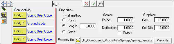
The Spring install methods are used to ensure the springs carry the proper loads at the input position of the suspension. You can use one of three methods as summarized in the table below and in full detail in the following sections:
Method |
Description |
Sketch |
|---|---|---|
Points |
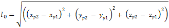
The distance between Points 1 and 2 fixes the initial length of the Spring and hence its force. Any changes in the location of Points 1 and 2 affect the Spring’s length, initial force, and line of action. The initial length (
|
|
Length |
You enter the length of the Spring to fix its load. Altering the locations of Points 1 and 2 changes the line the Spring acts along, but not the Springs initial length and force. |
|
Force |
Enter the initial force in the Spring. Any changes in the locations of Points 1 and 2 only affect the Spring’s line of action. Further, changes to the Spring properties like free length and stiffness do not affect the initial force. At initialization of the solver an iterative method is used to determine the Spring length that yields the entered force. |
|
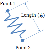
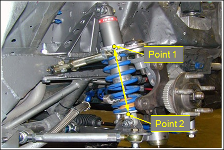
Select the Points radio button to use the distance between Points 1 and 2 as the initial length of the Spring. This is the typical choice when the points are located at the center of the upper and lower Spring seats as shown in the figure below:
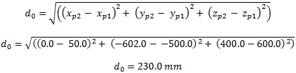
ExampleGiven point locations and linear Spring properties as shown in the table below, one can calculate the initial force in the Spring using the following equation:
Where:
Note the quantity
First calculate the distance between the points:
Next calculate the initial Spring force:
Note a positive force acts to push the points apart. |
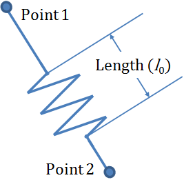
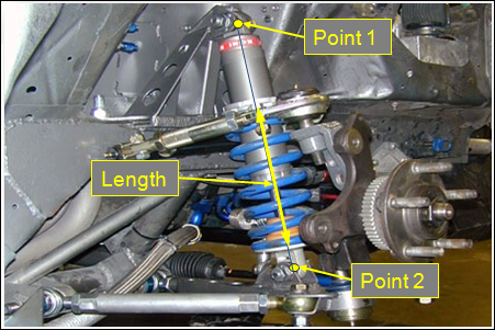
Select the Length radio button to enter the length of the Spring at the input position of the Point 1 and Point 2. For example, if your suspension employs a Spring coil over damper arrangement you might use the upper damper and lower damper points to fix the line of action of the Spring (see the figure below). However the distance between these points is much greater than the length of the Spring, therefore the Spring force will not be correct. So select length and enter the actual length of the Spring. If the locations of Point 1 and Point 2 change, the initial Spring length remains the value you entered.
|
You enter the initial force in the Spring at the input position. Changes to the locations of Points 1 and 2 and to the Spring properties do not alter the force. The solver computes the initial Spring length that yields the entered force during the initialization phase prior to any analyses. The solver always computes the initial Spring length prior to any in order to account for all changes in the point positions or the Spring properties. |
![]()
Where:
|
is the Spring force. |
|
is the force scale. |
|
is the Akima interpolation function. |
|
is the displacement scale. |
|
is the Spring free length. |
|
is the instantaneous Spring length. |
Checking the Output check-box adds an output request for the Spring length, length-rate-of-change, the Spring force, and the direction cosines of the line passing through Point 1 and Point 2. The Spring length and length-rate-of-change is measured along the line between Point 1 on Body 1 and Point 2. The Spring force also acts along the same line. A positive Spring force acts to repel the bodies, while a negative Spring force acts to attract the bodies.
The table below summaries the output channels in the MotionSolve .mrf file.
TYPE |
Component |
Quantity |
|---|---|---|
REQSUB |
RESULT(2) |
Spring Length. |
|
RESULT(3) |
Rate-of-change-Spring-length. |
|
RESULT(4) |
Spring Force. |
|
RESULT(6) |
Global X direction cosin of Spring. |
|
RESULT(7) |
Global Y direction cosin of Spring. |
|
RESULT(8) |
Global Z direction cosin of Spring. |
The Spring properties are stored in a TeimOrbit format text file. When you submit your model to the solver, the solver reads the Spring properties file for use during the simulation. If the units in the Spring properties file differ from the model, the solver internally converts the Spring properties to model units. The properties file is unchanged.
The Spring properties file contains header, units, spring data, and curve blocks. The units block specifies the length, mass, force, time and angle units employed in the file. The spring data block holds the spring free length. The curve block holds table of deflection and force values.
Positive displacement in the Spring is compression. While positive force acts to push apart the two bodies the Spring connects. Thus when plotted the force (Y) vs. displacement (X) curve should lie in the first and third quadrants. An example TeimOrbit format spring properties text file is shown below: $--------------------------------------------------------------------HEADER [HEADER] FILE_TYPE = 'spr' FILE_VERSION = 4.0 FILE_FORMAT = 'ASCII' $---------------------------------------------------------------------UNITS [UNITS] LENGTH = 'mm' ANGLE = 'degrees' FORCE = 'newton' MASS = 'kg' TIME = 'second' $---------------------------------------------------------------SPRING_DATA [SPRING_DATA] FREE_LENGTH = 270.75 $---------------------------------------------------------------------CURVE [CURVE] { disp force} -300.0 -15000.0 -200.0 -12000.0 -150.0 -9000.0 -100.0 -6000.0 -50.0 -3000.0 -10.0 -600.0 0.0 0.0 10.0 600.0 50.0 3000.0 100.0 6000.0 150.0 9000.0 |