In this tutorial, you will learn how to create a definition based entity (such as a system) using MDL.
Using systems allows you to:
| • | Organize your model file modularly |
| • | Reuse system definition files |
| • | Easily debug and maintain your files |
| • | Create a library of modeling components |
| • | Perform certain operations on the entire system at once (for example; turning systems on/off, making the whole system compliant/rigid, translation, etc.). An operation, such as translation on a system, is automatically performed on all the subsystems within that system. |
The concept of system definition is analogous to the procedures/subroutines in a programming language.
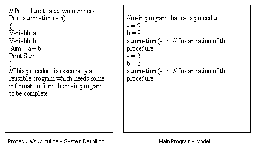
Analogy between programming and MDL approach
A procedure is a program that needs information from the main program. The procedure can be called /instantiated any number of times. A procedure is a part of main program, but can be maintained separately.
Similarly, a system definition is a model aggregate which needs information from the main model. It can be called/instantiated any number of times. A system definition is a part of the main model which can be maintained separately.
Use of system definition is two-step process:
| 2. | Instantiation of the system definition in the model |
Section 1: System Definitions
A system definition is a reusable system model that can be a part of any model as long all the attachment requirements are satisfied.
A system definition is represented by a *DefineSystem() block. This block should end with a *EndDefine() statement that indicates the end of a definition block. All entities defined within this block are considered to be part of the system definition.
A typical system definition example is shown below:
*DefineSystem(def_sys, att_1, att_2…att_n)
In the system definition example above:
| - | def_sys is the variable name of the system definition and will be used while instantiating this system. |
| - | att_1, att_2, … att_n is a list of arguments that act as attachments to the system. |
A system definition can be created in two ways:
| 2. | Created from graphical user interface. This requires minimal text editing. Refer to tutorial MV-1032. |
Note This tutorial covers Method 1, as it covers all the details of the system definition.
Section 2: System Attachments
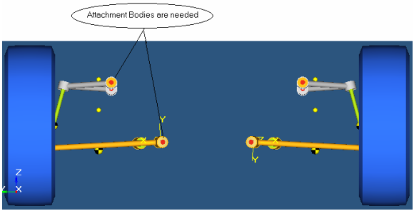
The picture above shows a system definition of an SLA suspension. It is an incomplete system which needs information about the attachment bodies and points to get connected to.
Excluding the *Attachment() statement, other entities in a system definition are similar to an MDL model file.
The general structure of a system definition is:
| • | A system receives information about entities external to the system via attachments. |
| • | Any MDL entity can be passed to a system as an attachment. |
| • | The *Attachment() statement inside the system definition declares the arguments in the *DefineSystem block as an attachment, along with assigning what type of entity the attachment is going to be. |
| • | The same variable name as the attachment should be referred within the definition when defining an entity that depends on the external entity. |
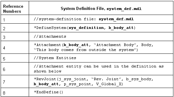
| • | Refer to the entries in bold in the example below. Reference line numbers are for reference only and are not part of the MDL file. |
| o | Line 2 - defines a system with a variable name sys_definition and has one argument b_body_att as an attachment. |
| o | Line 4 - declares b_body_att as an attachment with the entity type as Body. |
| o | Line 7 - creates a revolute joint between b_sys_body which is a body defined within this system (not shown) and b_body_att which is a body that is an attachment to this system. |
| Note | An attachment entity need not serve as a physical attachment to entities inside the system definition. It may be used to represent external variables being passed into the system definition. For example, datasets may also serve as attachments. |
Section 3: Instantiating a System
| • | Instantiating a system means creating an instance of a system definition. A system is instantiated using a *System() MDL statement, which has the following syntax: |
| o | *System(varname, “label”, def_varname, arg_1, arg_2, …, arg_n) where, |
| ▪ | varname – variable name of the system instance. |
| ▪ | label – descriptive label for the system. |
| ▪ | def_varname – variable name of the system definition being instantiated. |
| ▪ | arg_1, arg_2,… arg,_n – entity variable names that act as attachment to the system. The number of arguments should match the number of attachments listed and declared in the system definition. |
| • | A definition can be instantiated multiple times. For example, a single system definition file for an SLA suspension can be used to create multiple SLA suspension systems within one or more vehicle model files. |
| • | The following example illustrates a system definition and its instantiation within an MDL model file. Some of the terms in the example below are in bold to highlight a few key relationships between a system definition and its instantiation. Reference numbers are for the example only, and are not contained in an MDL file. |
| o | A system instance with variable name system1 is created in line 2, that refers to the definition sys_definition. B_Ground (Ground Body) which is passed as an argument for the attachment. |
| o | The system definition is described within the *DefineSystem() and *EndDefine() block between line 3 and line 7. Attachment b_att gets resolved to B_Ground. |
Reference Numbers
|
System Instantiation with Definition
|
1
|
// Model : Body.mdl
*BeginMDL(base_model, "Base Model")
|
2
|
//Instantiate the system definition sys_definition
*System(system1, "First System", sys_definition, B_Ground)
|
3
|
//Begin System Defintion Block
*DefineSystem(sys_definition, b_att)
|
4
|
//Declare a body attachment to the system
*Attachment(b_att, "Body Attachment", Body, "Add an body external to this system")
|
5
|
//Entities within the system
*Point(p_sys, "Point in the system")
*Body(b_sys, "Body in the system")
|
6
|
//Define a joint with the body b_sys and the body attachment b_att
*RevJoint(j_rev, "Revolute Joint", b_sys, b_att, p_sys, VECTOR, V_Global_X)
|
7
|
*EndDefine() //End Definition Block
|
8
|
*EndMDL()
|
You can instantiate systems within your model in one of three ways:
| 1. | Manually author the MDL file as shown in the example above. |
| 2. | Import a system from the System/Assembly panel in the MotionView MBD Model window. |
| 3. | Use the Assembly Wizard in the MotionView MBD Model window. |
The exercises that follow explain the first two methods; the third is covered in a separate tutorial.
Exercise 1: Creating and Using System Definitions
The following exercise illustrates how system definition can be generated from the original system MDL file. The later part of the exercise shows two different ways of system instantiation.
The following MDL statements are used in this exercise:
*DefineSystem()
*System()
*SetSystem()
*Attachment()
Problem
In Steps 1 and step 2:
| • | Modify the pendulum model from tutorial MV-1060 to create a pendulum system definition file called sys_pendu.mdl. |
| • | Use this system definition to add another pendulum to the pendulum model from the tutorial MV-1060 to obtain the double pendulum model shown in the figure below. |
| • | Save your base model file as doublependulum.mdl. |
| • | Perform a dynamic simulation of the transient response and view the animation. |
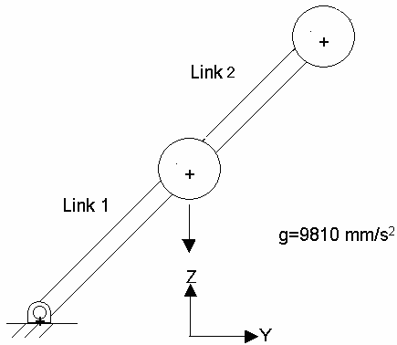
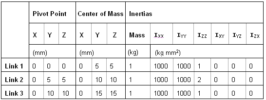
Schematic representation of the double pendulum
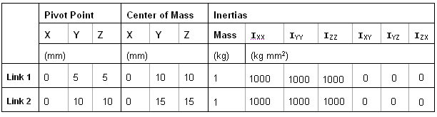
Properties table for the double pendulum
Step 1: Create a system definition.
The structure of a system definition is similar to an MDL model file. You can reuse the pendulum model file you created in the previous exercise to generate a more generalized system definition.
| 1. | Copy the pendulum.mdl file, located in the mbd_modeling\mdl folder, to your <working directory>. |
Below is a sample MDL file for the pendulum model in tutorial MV-1060.
//Pendulum Model
//05/31/XX
*BeginMDL(pendulum, "Pendulum Model")
//Topology information
//declaration of entities
//Points
*Point(p_pendu_pivot, "Pivot Point")
*Point( p_pendu_cm, "Pendulum CM")
//Bodies
*Body(b_link, "Ball", p_pendu_cm)
//Graphics
*Graphic(gr_sphere, "pendulum sphere graphic", SPHERE, b_link, p_pendu_cm, 1)
*Graphic(gr_link, "pendulum link graphic", CYLINDER, b_link, p_pendu_pivot, POINT, p_pendu_cm, 0.5, CAPBOTH)
//Revolute Joint
*RevJoint(j_joint, "New Joint", B_Ground, b_link, p_pendu_pivot, VECTOR, V_Global_X)
//Output
*Output(o_pendu, "Disp Output", DISP, BODY, b_link)
//End Topology
// Property Information
*SetPoint(p_pendu_pivot, 0, 5, 5)
*SetPoint(p_pendu_cm, 0, 10, 10)
*SetBody( b_link, 1, 1000, 1000, 1000, 0, 0, 0)
*EndMDL()
You can convert the above MDL file into a system definition by making small changes to your MDL file. It is important to note that this conversion is not applicable in all cases, and some of the conditions that need to be taken care are described later in this tutorial.
| 2. | Replace the *BeginMDL() and *EndMDL() statements with the *DefineSystem() and *EndDefine() statements, respectively. Specify an appropriate variable name for the system definition. |
| 3. | The pendulum system definition would need information about: |
| - | Where to connect (attachment point or pivot point) |
| - | What body to connect to (attachment body) |
Let’s use att_point and att_body as the attachment entities.
| 4. | Use these variables in the *DefineSystem () statement: |
*DefineSystem (sys_def_pendulum, att_point, att_body)
| Note | As mentioned earlier, the attachment entity can be any MDL entity. Therefore one needs to specify the entity type that the variable represents (for example, att_point represents the POINT entity). |
| 5. | Use *Attachment statement to specify the entity type that each variable represents. |
*Attachment (att_point, "Pivot Point", POINT, "Attachment point where the pendulum definition gets attached")
*Attachment (att_body, "Attachment body" , BODY, " Any body to which the pendulum definition gets attached")
| Note | In the original model variable p_pendu_pivot was representing the pivot point. While converting the pendulum model to pendulum system definition, this pivot point would be provided by the attachment point. |
| 6. | The point p_pendu_pivot is now passed as an attachment, therefore we do not need to define the pivot point. Delete the statement *Point (p_pendu_pivot, "Pivot Point"). |
| 7. | Retain pendulum CM point as it is. |
| 8. | Retain the *Body() statement to create the pendulum body. |
The *RevJoint() statement refers to the B_Ground and p_pendu_pivot. Replace B_Ground with the att_body and p_pendu_pivot with att_point.
| 9. | Retain the sphere *Graphic() statement. |
The *Graphic() statement for the cylinder refers to the variable p_pendu_pivot. Replace the variable p_pendu_pivot with att_point.
| Note | All of these variable replacements show that wherever applicable, the attachment variables should replace the original variables. |
| 10. | Retain the *Output() statement. This allows you to obtain displacement outputs on each pendulum body in your model. |
| 11. | Remove *setpoint(p_pendu_pivot, 0, 5, 5). |
| 12. | Parameterize the points in the system so that they are positioned with respect to each other in a certain way. In this case, you can set the CM point to be 5 units away from the attachment point in the y and z direction (att_point.y+5, att_point.z+5). |
| 13. | The following file shows a sample system definition (system.mdl): |
// system.mdl
// created on:
*DefineSystem(sys_def_pendulum, att_point, att_body)
//Topology Data
// Declaration of Entities
//Attachments
*Attachment (att_point, "Pivot Point", Point, "Attachment point where the pendulum definition gets attached")
*Attachment (att_body, "Attachment body" , Body, " Any body to which the pendulum definition gets attached")
//Points
*Point( p_pendu_cm, "Pendulum CM")
//Bodies
*Body(b_link, "Ball", p_pendu_cm)
//Joints
*RevJoint(j_joint, "New Joint", att_body, b_link, att_point, VECTOR, V_Global_X)
//Output
*Output(o_pendu, "Disp Output", DISP, BODY, b_link)
//Graphics
*Graphic(gr_sphere, "pendulum sphere graphic", SPHERE, b_link, p_pendu_cm, 1 )
*Graphic(gr_link, "pendulum link graphic", CYLINDER, b_link, att_point, POINT, p_pendu_cm, 0.5, CAPBOTH )
|
// Property Data
*SetPoint(p_pendu_cm, 0, att_point.y+5, att_point.z+5)
*SetBody(b_link, 1, 1000, 1000, 1000, 0, 0, 0)
*EndDefine()
|
| 14. | Save the file as sys_pendu.mdl. |
Step 2: Add a system definition by manually authoring your MDL file.
In step 1, you created a reusable system definition. In this step, you will instantiate this system definition in your model file. In the manual approach, you will write an MDL file which includes the system definition and instantiates it several times.
| 1. | Create a new empty file in a text editor. |
| 2. | Begin the model file with a *BeginMDL() statement. |
| 3. | Copy the content in the sys_pendu.mdl file from*DefineSystem() to *EndDefine() after the *BeginMDL() statement. |
| 4. | Instantiate the first pendulum system using the *System() statement. Refer to the MDL Language Reference online help for syntax. For example: |
*System(system1, "First Pendulum System", sys_def_pendulum, P_Global_Origin, B_Ground)
When you instantiate a system, remember:
| • | Reference the system definition used by the system by specifying its variable name as the third argument in the *System() statement. The variable name of the system definition should be the same as you specified in the corresponding *DefineSystem() statement. In the above example, system1 uses the system definition sys_def_pendulum. |
| • | If the system definition contains attachments, resolve those attachments when you instantiate the system. For example, sys_def_pendulum has an attachment, att_body, to reference body_2 in the *RevJoint() statement. In system1, the pendulum body, b_link, should be connected to the ground body, B_Ground. Therefore, B_Ground is specified as the attachment body in the *System() statement. |
| • | It is recommended to add the *System() statement before *DefineSystem(), although this not mandatory. |
| 5. | Repeat Step 4 with appropriate modifications, to create the second pendulum system using the *System() statement again. |
| • | Provide a different variable name, system2, for the system instance. |
| • | Use Pendulum CM (p_pendu_cm) and the Pendulum Body (b_link) from the first system as the attachment. |
The exact statement that you should use is shown below:
*System(system2, "Second Pendulum System", sys_def_pendulum, system1.p_pendu_cm, system1.b_link )
| 6. | Close the MDL file with the *EndMDL() statement. |
A sample MDL file is provided below:
*BeginMDL(model, "MODEL")
*System(system1, "First Pendulum System", sys_def_pendulum, P_Global_Origin, B_Ground)
*System(system2, "Second Pendulum System", sys_def_pendulum, system1.p_pendu_cm, system1.b_link )
*DefineSystem(sys_def_pendulum, att_point, att_body)
//Topology Data
// Declaration of Entities
//Attachments
*Attachment (att_point, "Pivot Point", Point, "Attachment point where the pendulum definition gets attached")
*Attachment (att_body, "Attachment body" , Body, " Any body to which the pendulum definition gets attached")
//Points
*Point( p_pendu_cm, "Pendulum CM")
//Bodies
*Body(b_link, "Pendulum Body", p_pendu_cm)
//Joints
*RevJoint(j_pivot, " Revolute Joint at Pivot Point ", b_link, att_body, att_point, VECTOR, V_Global_X)
//Output
*Output(o_pendu, "Disp Output", DISP, BODY, b_link)
//Graphics
*Graphic(gr_sphere, "pendulum sphere graphic", SPHERE, b_link, p_pendu_cm, 1 )
*Graphic(gr_link, "pendulum link graphic", CYLINDER, b_link, att_point, POINT, p_pendu_cm, 0.5, CAPBOTH )
// Property Data
*SetPoint(p_pendu_cm, 0, att_point.y+5, att_point.z+5)
*SetBody(b_link, 1, 1000, 1000, 1000, 0, 0, 0)
*EndDefine()
*EndMDL()
| 7. | Save the model as doublependulum.mdl. |
| 8. | Open the MDL file in MotionView and review the model. |
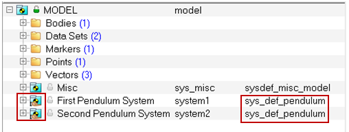
| 9. | Take a close look at items listed in the Project Browser. You will now notice a 'hand' under the System icon for the First Pendulum System and the Second Pendulum System. This indicates that both of these systems share a single definition. This feature is called a Shared Definition. |
| 10. | When a System definition is shared among different instances, any modifications to one of those instances can be made to reflect in all of the instances. This can be achieved as follows: |
| - | From the Tools menu, select Options. |
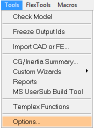
The Options dialog is displayed.
| - | Click on the Build Model option (located near the bottom of the tree). |

| 11. | Under Legacy Support, uncheck the Create a separate definition when modifying a shared instance option. This will ensure that when entities in a shared instance are modified, the changes will be reflected across all of the instances without creating a separate definition. |
| 12. | Click OK to close the dialog. |
| 13. | Run the MotionSolve simulation and post-process the results. From the Main tab of the Run Panel  , specify the End time as 1.0 and the Print interval as 0.01. , specify the End time as 1.0 and the Print interval as 0.01. |
Exercise 2: Adding Systems from the Systems/Assembly Panel
This exercise demonstrates how to instantiate a system from the MotionView graphical user interface using the Systems/Assembly panel.
Problem
In this exercise:
| • | Use MotionView to add another pendulum link to your double pendulum model to obtain the triple pendulum shown in the image below. |
| • | Solve and view the animation. |
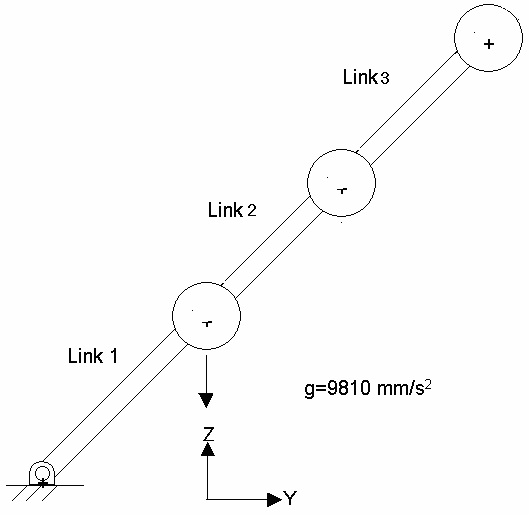
The triple pendulum
Properties table for the triple pendulum
Step 1: Add the system definition from MotionView.
Adding system definitions to a model is similar to adding other entities except the system definitions are loaded from a file.
| 1. | Start MotionView and open the pendulum model file from Exercise 1 (the previous exercise) in the MBD Model window. |
| 2. | From the Project Browser, click Model. |
The Systems/Assembly panel is displayed.
| 3. | Click the Import/Export tab. |
| 4. | Using the Select File: file browser  , pick the system definition you just created, sys_pendu.mdl. , pick the system definition you just created, sys_pendu.mdl. |
The Specify entity details dialog is displayed.
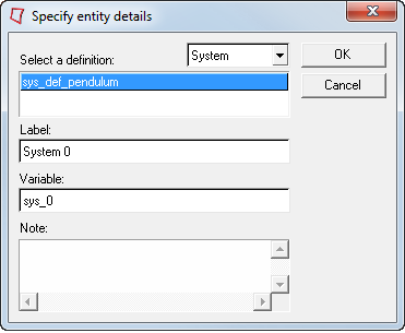
| 6. | Under Select a definition, select sys_def_pendulum. |
| 7. | Under Label, remove the default label and enter Third Pendulum System as the new label. |
| 8. | Under Variable, remove the default variable and enter system3 as the new variable. |
Step 2: Resolve attachments and update points.
| 1. | Select the newly added system from the Project Browser. |
The *Attachment() line added to the system definition now appears in the Attachments tab for the system folder of the newly added system. Attach the third link of the pendulum to the second link in the pendulum system.
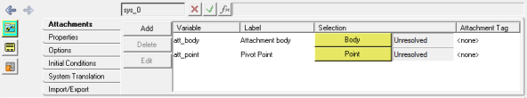
| 2. | From the Attachments tab, activate the  collector for Attachment body to select a body attachment. collector for Attachment body to select a body attachment. |
The Select a Body dialog is displayed.
| 3. | Expand the Bodies folder in the second pendulum system and pick the Pendulum Body (which belongs to system2). |
| 5. | Next, activate the  collector for Pivot Point to select a point attachment. collector for Pivot Point to select a point attachment. |
The Select a Point dialog is displayed
| 6. | Expand the Points folder under the second pendulum system and select the Pendulum CM point. |
The third pendulum system should be visible in the graphics area.
| 8. | Save the model as triplependulum.mdl for future use. |
| 9. | Run MotionSolve and view the results. |
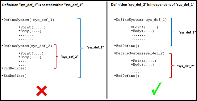
Important Note Regarding Definitions:
One important aspect of definitions is that they need to be independent, therefore a *DefineXXX block should not contain another *DefineXXX block within them. For example, the figure on the left (below) shows a *Define block inside another *Define block. Such definitions are referred as nested definitions and may result in MotionView giving errors while reading such definitions. The figure on the right shows the correct way of placing definitions.
In Exercise 1, the method to author a system definition is described by modifying an existing model MDL, in other words replacing *BeginMDL() and *EndMDL() with *DefineSystem() and *EndDefine(). While this method can be employed in many cases, care should be taken so that any existing definition block within the *BeginMDL block should not end up being nested as described above. Such a definition block must be moved out of the block so that the definition blocks are independent with regard to each other.


