|
»Click here to display Table of Contents«
|

Force |

|

|

|

|
|
Force |
|
|

|

|
|
»Click here to display Table of Contents«
|
Force |
|
|
|
|
|
Force |
|
|
|
|
This section describes the Force entity of MotionView and shows the various usage, creation, and editing methods.
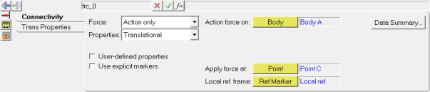
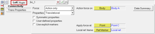
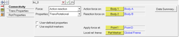
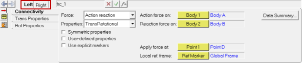
A Force entity, as the name suggests, is used to apply a force and/or a torque on a body. The created Force can be of the type Action only or Action reaction. An Action only force acts on a single body on which force is applied. An Action reaction force acts on two bodies, one is called the action body and the other the reaction body.
Common Applications of Forces are:
| • | External force like aerodynamic force on a vehicle body |
| • | Jounce and rebound bumper elements |
| • | Steering torque, etc. |
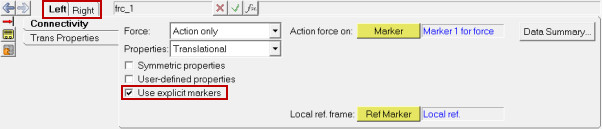
The topological information required to define a Force is shown in the figures below:
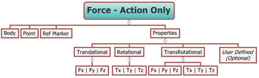
The data members of the Force can be classified into the following members:
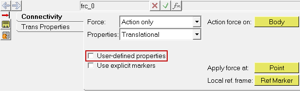
An Action only Force needs the following:
| • | Body - on which the force is applied. |
| • | Point – on which the force is applied. |
| • | A local reference frame (Ref Marker) - which defines the orientation of the force. |
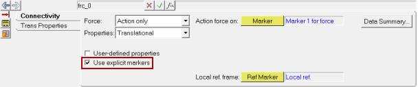
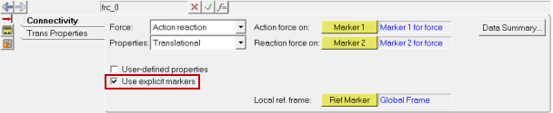
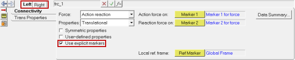
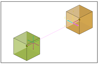
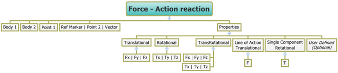
An Action reaction Force needs the following:
| • | Two Bodies (Body 1 and Body 2) – between which the force acts. |
| • | Point 1 - the location at which the force is applied. |
| • | A local reference frame (Ref Marker) - which defines the orientation of the force. |
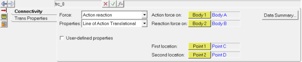
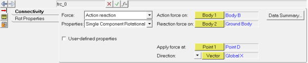
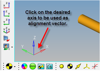
An Action reaction force can be a Line of Action Translational type or a Single Component Rotational type, in which case the following would need to be specified:
| • | Two Bodies (Body 1 and Body 2) – between which the force acts. |
| • | Point 1 - the first location defines the line of action or point of application in the case of Single Component Rotational torque. |
| • | Point 2 - the second location that completes the line definition or Point/Vector that defines the rotational axis of the of Single Component Rotational torque. |
A Force/Torque can only be modeled as a Single entity or as a Pair entity.
A Force in MotionView can be defined as Translational, Rotational (torque), TransRotational (combination of force and torque), Line of Action Translational, or Single Component Rotational type. These properties can be assigned to the Force using appropriate tabs that appears based on the selections in the Connectivity tab. A topology map of the Force properties is shown in the figure below:
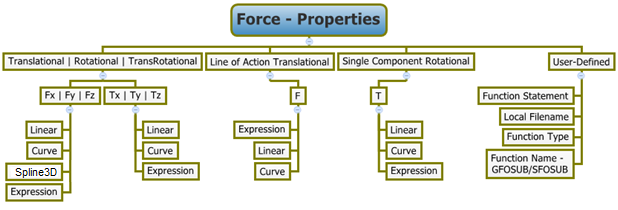
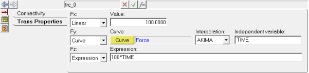
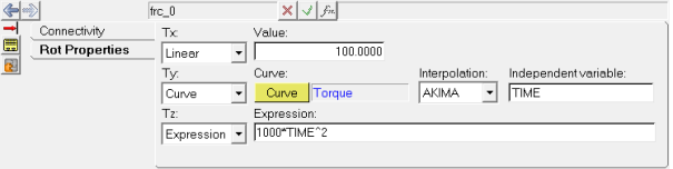
Force/Torque properties can be defined along/about three axes of the local reference marker using the Fx/Tx, Fy/Ty, and Fz/Tz fields in the Properties tab. In case of a Line of Action translational force, the line defines the direction of application and the property can be defined in a single field provided. The same is true for a Single Component Rotational torque.
Force translational properties, Torque rotational properties, Line of Action Translational, and Single Component Rotational forces can all be of the same following types:
| • | Linear |
| • | Curve |
| • | Spline3D |
| • | Expression |
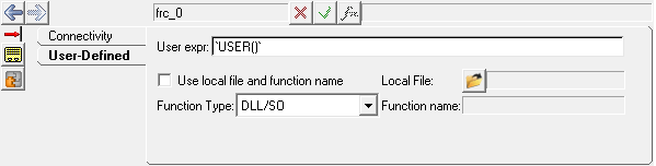
Alternatively, force properties can also be applied using User-defined properties. User-defined properties need the following:
| • | A User Function Statement |
| • | A Local filename for the Subroutine DLL or script file |
| • | Function Type – DLL/SO, Python, Matlab |
| • | Function Name - SFOSUB/GFOSUB |
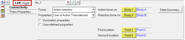
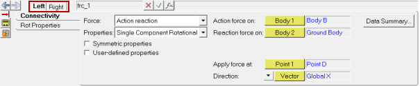
| Note | When modeled as a Pair entity, the Linear properties of the Force can be made symmetric. |
To learn how to add a Force to a model, please see the Entity Manual topic. Once a Force has been added to the model using any of the "entity" creation methods, the panel for the force is automatically displayed and available for editing (see Step #2 in the To select and edit a Force entity section below).
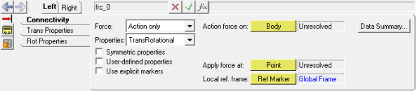
Forces Panel – Connectivity Tab - Pair Entity - TransRotational Force
The graphics area selection is now filtered to pick a Force entity. Also, if the Filter Using Toolbar option is selected in the Project Browser context menu, the browser will now only display the Forces in the model.
The corresponding panel is automatically displayed and available for editing.
Note - The Properties tab(s) will automatically change into the User-Defined tab.
Note - The same steps as shown above can also be used to define Pair Force entities. When defining the properties of a Pair Force Entity, there is an option available to make the properties Symmetric or Asymmetric. When the Force is made Symmetric, you can choose to make the Left or Right side Force as the master side and other side will mirror those properties. In the case of Asymmetric properties, the Left and Right side of the properties must be defined individually. |
The model containing the Force can be saved in MDL format from MotionView and exported in the MotionSolve XML format.
The following MDL statement is used to specify the properties of the Force entity:
To learn how to create a complete model using MDL Statements please refer to tutorial MV-1060: Introduction to MDL. |
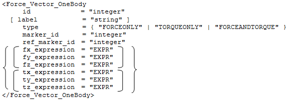
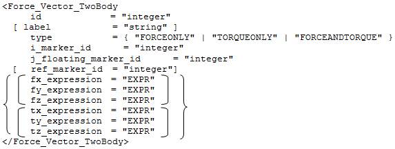
The Force entity when exported to the MotionSolve XML format is defined as a Force_Vector_OneBody statement for Action Only Force, Force_Vector_TwoBody for Action Reaction Force, and Force_Scalar_TwoBody for Line of Action Translational and Single Component Rotational Forces. A Pair entity created in MotionView is represented as two individual model statements when exported to the MotionSolve XML format.
In the above XML Model statement the i_marker_id represents the first or action Body for the force application and the j_floating_marker_id represents the second or reaction Body for the force application. To understand the complete syntax of the Force XML model statements, please refer to the MotionSolve Reference Guide Page for Force_Vector_OneBody, Force_Vector_TwoBody and Force_Scalar_TwoBody. |
In MotionView, Tcl can be used to add any MDL entities to the model. There are two Tcl commands that can be used to add an entity:
Syntax: mdlmodel_handle InterpretEntity new_handle keyword varname label Example: mdlmodel_handle InterpretEntity force_handle ActionReactionForce frc_0 "\"Force 1\"" TRANS b_0 b_1 p_0 marker_0; |
Syntax: mdlmodel_handle InterpretSet keyword tokens Example: mdlmodel_handle InterpretSet SetForce frc_0 LIN 100 LIN 100 LIN 100; |
The command InterpretEntity is used to add entities to the model and the command InterpretSet is used to set the entity properties. Extended definitions for InterpretEntity and InterpretSet can be found in the HyperWorks Desktop Reference Guide.
Note - When using the InterpretEntity and InterpretSet commands, it is important to also use the Evaluate command in order for the changes to take effect immediately.
To learn how to create a complete model using Tcl commands, please refer to tutorial MV-1040: Model Building Using Tcl.
The following example shows the various Force entities that are available in MotionView:
*BeginMDL( the_model, "Model", ) *StandardInclude(FILE) *Point( p_0, "Point A" ) *Point( p_1, "Point B" ) *Point( p_2, "Point C" ) *Point( p_3, "Point D" ) *PointPair( p_4, "Point A" ) *PointPair( p_5, "Point B" ) *PointPair( p_6, "Point C" ) *PointPair( p_7, "Point D" ) *Marker( m_0, "Local ref.", b_0, p_2 ) *MarkerPair( m_1, "Local ref.", b_2, p_6 ) *Body( b_0, "Body A", p_0, , , , ) *Body( b_1, "Body B", p_1, , , , ) *BodyPair( b_2, "Body A", p_4, , , , ) *BodyPair( b_3, "Body B", p_5, , , , ) //Example for Force statements *ActionOnlyForce( frc_0, "Force ActionOnly", TRANS, b_0, p_2, m_0 ) *ActionReactionForce( frc_1, "Force ActionReaction", TRANS, MARKERS, m_2, m_3, Global_Frame ) *ActionReactionForce( frc_2, "Force LOA", LOA, b_0, b_1, p_2, p_3 ) *ActionReactionForce( frc_3, "Torque Single Component Rot.", SC_ROT, b_1, B_Ground, p_3, VECTOR, V_Global_X ) *ActionOnlyForcePair( frc_4, "Force ActionOnly", TRANS, MARKERS, m_4, m_1 ) *ActionReactionForcePair( frc_5, "Force ActionReaction", TRANS, MARKERS, m_4, m_5, Global_Frame ) *ActionReactionForcePair( frc_6, "Force LOA", LOA, b_2, b_3, p_6, p_7 ) *ActionReactionForcePair( frc_7, "Torque Single Component Rot.", SC_ROT, b_3, B_Ground, p_7, VECTOR, V_Global_X ) *Marker( m_2, "Marker 1 for force", b_0, p_2 ) *Marker( m_3, "Marker 2 for force", b_1, p_3 ) *MarkerPair( m_4, "Marker 1 for force", b_3, p_6 ) *MarkerPair( m_5, "Marker 2 for force", b_2, p_7 ) *SetPoint( p_1, 400 ) *SetPoint( p_0, 0 ) *SetPoint( p_2, 50 ) *SetPoint( p_3, 350 ) *SetPoint( p_4, LEFT, 400, -200 ) *SetPoint( p_5, LEFT, 0, -200 ) *SetPoint( p_6, LEFT, 50, -200 ) *SetPoint( p_7, LEFT, 350, -200 ) //Example for setting force properties *SetForce( frc_0, LIN, 100, LIN, 200, LIN, 250 ) *SetForce( frc_2, EXPR, `100*TIME` ) *EndMDL() |
See Also:
*ActionOnlyForce (MDL Model Statement)
*ActionOnlyForcePair (MDL Model Statement)
*ActionReactionForce (MDL Model Statement)
*ActionReactionForce - line of action (MDL Model Statement)
*ActionReactionForce - single component rotation (MDL Model Statement)
*ActionReactionForcePair (MDL Model Statement)
*ActionReactionForcePair - line of action (MDL Model Statement)
*ActionReactionForcePair - single component rotation (MDL Model Statement)
Force_Scalar_TwoBody (XML Command)
Force_Vector_OneBody (XML Command)
Force_Vector_TwoBody (XML Command)
InterpretEntity (Tcl Command)
InterpretSet (Tcl Command)