This section provides a detailed description about the creation, modification, and usage of the various MotionView entities, their panels and attributes, and the features used for pre-processing MBD models.
A complete list of entities that can be created in MotionView is shown below:
The MotionView User Interface follows a common theme for adding/modifying/deleting entities.
| Note | Not all of the all of the entities available in MotionView are covered in this section. |
Adding Entities
There are two ways to add entities to a MotionView model:
| • | Using the MotionView Toolbar |
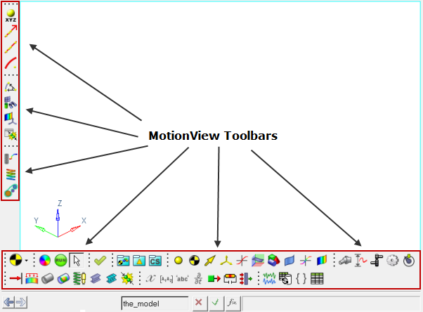
MotionView Toolbars With All Of The Entity Panel Icons Displayed
| • | Using the MotionView Project Browser |
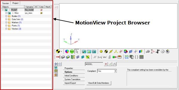
MotionView Project Browser
| 1. | From the Project Browser, select a container entity folder (such as System, Assembly, Analysis) into which the entity is to be added. |
| 2. | Locate the icon for the entity to be added on the MotionView toolbar (mouse over the icon to display a tool tip text). |
| 3. | Right-click on the icon. |
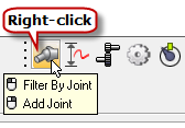
Right-click to Add an "Entity"
| 4. | The Add "Entity" dialog is displayed, which allows you to specify various information about the entity being added to the model (see below). |
|
| 1. | From the Project Browser, right click on a container entity folder (such as System, Assembly, Analysis) into which the entity is to be added. |
The browser context menu is displayed which contains menu items to add entities. These entities are grouped as per the classification shown in the table above, for example to add a Point, select Add > Reference Entity > Point.
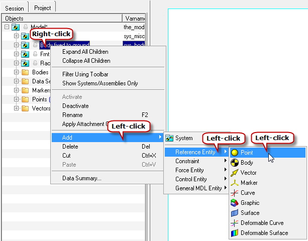
Right-click on the Container Entity to Add Child Entities
| 2. | The Add "Entity" dialog is displayed, which allows you to specify various information about the entity being added to the model (see below). |
|
The Add "Entity" Dialog
Both the Toolbar and Project Browser methods for adding entities (discussed above) will lead to the Add "Entity" dialog being displayed.
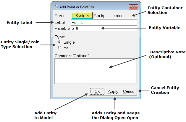
The Add "Entity" dialog is used to specify the following information about the entity being added:
Parent
|
Specifies the parent container for the entity being added. If the currently selected parent is incorrect, you have the option to pick a different parent container by clicking on the container collector.
The Select a System or Assembly or Analysis dialog is displayed.
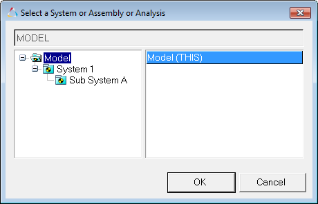
Use the selection tree to select a new parent container.
|
Label
|
Specify a meaningful label for the entity. The Label can be any descriptive name that clearly identifies the entity being added and its relevance in the model. The label can be alphanumeric, and it can also contain special characters and spaces.
|
Variable
|
Variable name (also referred to as "varname" in short) is a primary attribute of an entity through which MotionView addresses that entity. Any reference to the entity by another entity is made using the variable name.
A variable name for an entity has to be unique within the container into which it is being created:
| - | Alphanumeric characters are allowed. |
| - | No spaces or other special characters allowed except "_" (underscore). |
| - | Each entity has standard attributes such as: varname, id, idstring, state, etc. Usage of these strings as variable names is prohibited. |
|
Type
|
Most entities in MotionView can be defined as pairs. Use this option to specify if the entity being added is a single or a pair entity (whose properties can be made symmetric about the ZX plane of the model).
|
Comment
|
An optional field, where more general information about the entity can be provided.
|
OK
|
Adds the entity to the model and closes the dialog.
|
Cancel
|
Cancels the creation of the entity and closes the dialog.
|
Apply
|
Adds the current entity to the model and keeps the dialog open to allow additional entities (of the same type) to be added.
|
Once the entity is added, the corresponding entity panel is displayed where the various properties can be specified.
Modifying Entities in the Model
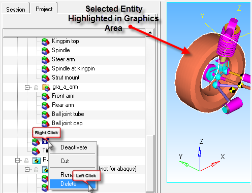
To modify properties of an entity, the entity needs to be selected. The following takes place when an entity is selected:
| • | its corresponding panel (with properties) is displayed |
| • | its graphical representation (if exists) on the screen is highlighted with white border |
| • | the entity selection is indicated in the browser with its font having a blue or gray background. |
Entities can be selected using the following methods:
| • | the context menu in the graphics area |
| • | navigating using a hyperlink from a different entity panel in which the entity is referenced |
The figure below shows an example of the context menu that is displayed after right-clicking on an entity in the MotionView graphics area:
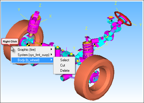
The menu options that are displayed vary and depend upon the entities underneath the mouse pointer at the time of the right-click. In the example above, the right-click was done on the Tire Graphic at which there are three entities:
| - | Graphic (tire) – the Tire graphic |
| - | System (sys_frnt_susp) – the parent container in which the Tire graphic belongs to |
| - | Body (b_wheel) – the parent body of the Tire graphic |
Use the Select sub-menu option to select the entity.
|
For any model in MotionView, in the Project Browser right-click the label of the entity that needs to be deleted from the model. The context menu as shown in the figure below will be displayed:
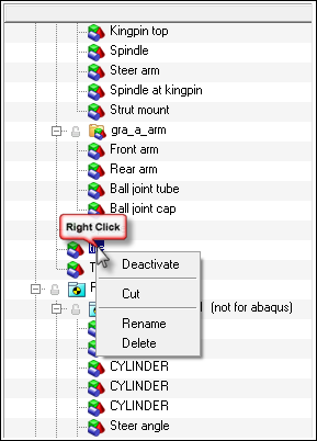
Entity - Project Browser Context Menu
The following options are available on the context menu:
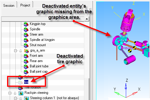
Deactivate
|
Deactivates the entity in the model. When an entity is deactivated, even though it is present in the model it cannot be used a part of any entity definition, nor will it be exported to the Solver file. This is a very useful option when debugging the model for errors. A deactivated entity will disappear from the graphics area. The entity will still be seen in the Project Browser, but the entity icon preceding its label will be shown in dull colors (as shown in the figure below).
|
Cut
|
Cuts the entity from its current container so that it can be pasted in another container if required.
|
Rename
|
Allows you to change the Label of the entity.
|
Delete
|
Deletes the entity from the model (see the example below):
|
|
Model Parameterization
Parameterization is an easy way to describe a model in terms of its design variables (see the examples below):
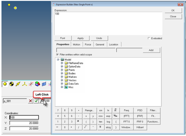
The properties of a Point entity can be parameterized with respect to other model properties. The main benefit of parameterizing point properties is that the coordinates of points can automatically change when the controlling parameters change.
Consider the following case where the following two points are in the model:
| • | Point A - where the X, Y, Z coordinates of the point are 100, 0, 0 respectively. |
| • | Point B - where the coordinates of the Point B are such that X coordinate value should be 100 units more than X coordinate value of Point A. |
For this case the coordinates of the points can be parameterized in this way:
Point B = X coordinate of Point A + 100, Y coordinate of Point A, + Z coordinate of Point A
The MDL syntax for the above parameterization is:
// Point A and its Coordinates //
*Point(p_a, “Point A”)
*SetPoint(p_a, 100, 0, 0)
//Point B and its Parameterized Coordinates//
*Point(p_b, “Point B”)
*SetPoint(p_a.x+100, p_a.y, p_a.z)
Thus the coordinates of Point B will become 200,0,0 and will always depend on the coordinates of Point A.
|
Parameterization can be set up using any of the "entity" editing methods discussed above. The Expression Builder can be a very useful tool for setting up parameterization in MotionView models. Click the F(x) button,  , in the Points panel to invoke the Expression Builder: , in the Points panel to invoke the Expression Builder:
|
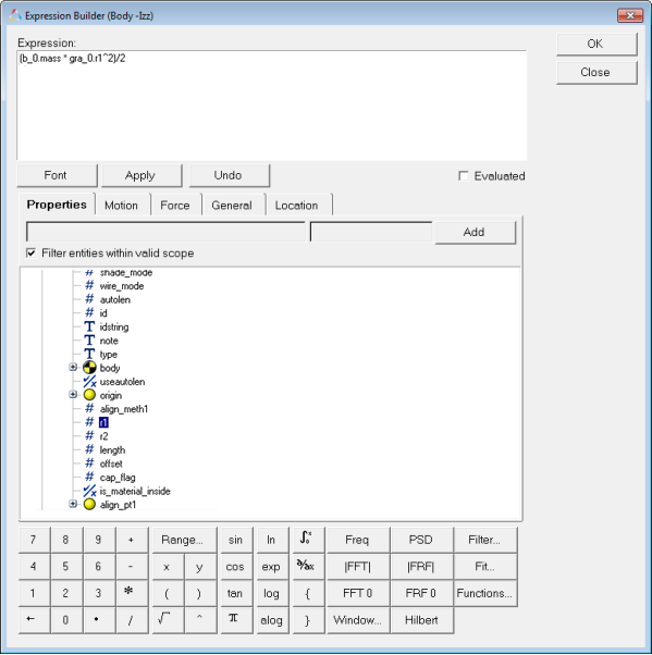
The properties of a Body entity can be parameterized with respect to other model properties. The main benefit of parameterizing body properties is an increase in the ease of modeling.
Some of the most commonly used parameterizations for Body entities are:
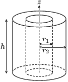
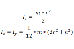
| 1. | Mass and Inertia Properties of the body are parameterized using formulas that depend on the graphics added to the body. For example if a body has a cylinder graphic - then the Moment of Inertia of the body can be calculated using the formulas given below: |
| 2. | The values of r and h in the above equations can be obtained from the radius and height of the cylinder graphic. The various values can be obtained using the paths given below: |
Body Mass (m) = MODEL. b_0.mass
(where the b_0 is the variable name of the selected body)
Body Cylinder Radius (r) = MODEL.gra_0.r1
Body Cylinder Height (h) = MODEL.gra_0.length
(where the gra_0 is the variable name of the selected graphic)
|
So then the formula for Iz becomes Iz = (b_0.mass * gra_0.r1^2)/2
|
Various parameterizations of the body properties can be setup by extracting data from the other entity properties. The Expression Builder can be a very useful tool for setting up parameterization in MotionView models. Click the F(x) button, , in the Bodies panel to invoke the Expression Builder dialog:
Note - Parameterization can be set up using any of the "entity" editing methods discussed above.
|
Datasets is a modeling entity that is used collect information from the user or to show information to the user. This information can further be used in the model for parameterization of the model. Many entity properties in MotionView can be parameterized with the data in Datasets. A simple example is shown below to illustrate the usage of Datasets in the model.
| 1. | The Box graphic in MotionView needs three properties to complete the definition: Length X, Length Y, and Length Z which are the length, breadth, and height of the box graphic. |
| 2. | The three properties can be presented using a Dataset in such a way that the values can be changed in the dataset and the the Box dimensions will change according to the data entered. |
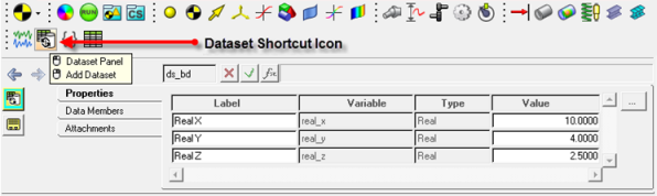
Dataset that can be used to Collect Box Dimensions Data from a User
| 3. | As shown in the figure above, the variable name of the dataset is ds_bd and the three data member variables are real_x, real_y, and real_z. |
| 4. | Each of the Data members of the Dataset shown above have a real value which can be set and changed by at any point in time during modeling. |
| 5. | These three values can be used as the values of Length X, Length Y, and Length Z mentioned in step 1 above. |
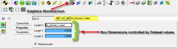
Box Graphic Properties using Values from the Dataset
| 6. | The figure above shows how the values of the Dataset’s data members are used as the properties of a Box Graphic. |
The Parameterized Expression to access the values of the Dataset are:
Box Length X = ds_bd.real_x.value
Box Length Y = ds_bd.real_y.value
Box Length Z = ds_bd.real_z.value
|
| 7. | The benefit of parameterization using a Dataset is that potentially many entities of a model can be controlled using a few datasets. |
|