The Deformable Surfaces panel allows you to create a surface that can change shape during the simulation. It can be used to model a PointToDeformableSurfaceJoint MDL entity or a PointToDeformableSurfaceContact MDL entity. The points that are used to describe the surface can belong to one or more bodies (rigid or flexible).
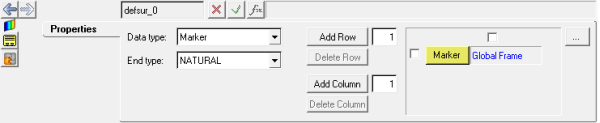
Deformable Surfaces panel - Properties tab
The following options are available on the Properties tab:
Data type
|
Select the type of locations to be used to describe the deformable surface.
|
|
Marker
|
Select Marker if the locations defining the surface are to be defined by marker entities.
|
|
Body/Point
|
Select Body/Point if the locations defining the surface are to be defined by sets of bodies and points, where MotionView will automatically create markers from these entities.
|
End type
|
Select one of the following methods: NATURAL, PARABOLIC, or PERIODIC. Please see the Comments section below.
|
Add Row
|
The number of rows shown in the field will be added after each row with an activated checkbox.
|
Delete Row
|
All rows with an activated checkbox will be deleted when this button is clicked.
|
Add Column
|
The number of columns shown in the field will be added after each column with an activated checkbox.
|
Delete Column
|
All columns with an activated checkbox will be deleted when this button is checked.
|
| 1. | From the Project Browser, select the system to which the deformable surface is to be added. |
| 2. | Right-click on a system folder in the Project Browser and select Add > Reference Entity > Deformable Surface from the context menu. |
OR
| - | Right-click on a deformable surface folder in the Project Browser and select Add Deformable Surface from the context menu. |
OR
| - | Right-click the Deformable Surfaces button  on the Reference toolbar. on the Reference toolbar. |
The Add Deformable Surface dialog is displayed.
| 3. | Assign a label to the surface in the Label field. |
The surface label can be changed at any time.
| 4. | Assign a variable name to the surface in the Variable field. |
The variable name is required and cannot be changed after it is defined.
| 5. | Enter any notes in the Note text box |
The deformable surface is added.
|
Comments
| 1. | This entity is applicable for Solver mode as MotionSolve only. |
| 2. | MotionSolve applies a cubic spline interpolation to represent the surface. |
The spline interpolation requires assumptions on the second derivative at the ends. The End type selected specifies the method of assumption for the second derivative.
For an interpolating function f(x) with N+1 points:
| • | NATURAL – The second derivative at both ends are considered equal [f”(x0) = f”(xN)] |
| • | PARABOLIC – The second derivative at each end is equated to its adjacent point [f”(x0) = f”(x1); f”(xN) = f”(xN-1)] |
| • | PERIODIC – The second derivative is periodic at the ends and can be used for periodic surfaces [f”(x0) = f”(xN-1); f”(x1) = f”(xN) |
See Also:
Deformable Curves Panel
Advanced Joints Panel
Contacts Panel
Reference_DeformSurface


