MotionView User's Guide

Bodies

Bodies

Previous topic Next topic Expand/collapse all hidden text  

Bodies

Previous topic Next topic JavaScript is required for expanding text JavaScript is required for the print function  

This section describes the Body entity of MotionView and shows the various usage, creation, and editing methods.

Theory/Background

The figure below shows the three types of Bodies (and their properties) available in MotionView for multibody systems:  Rigid, Point Mass, and Deformable.
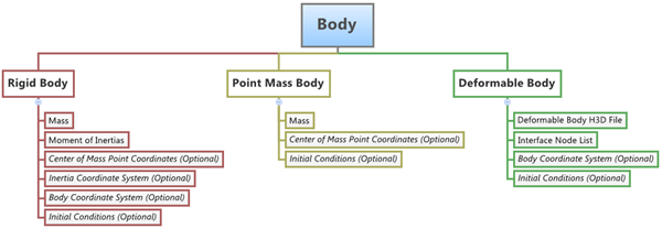
body_type_prop_diagram_mv

Rigid Body

In a multibody system, a Rigid body is an ideal representation of solid body/part of fixed size and shape in which deformation is insignificant or neglected, or in other words, the distance between any two points of a Rigid body remains unchanged (irrespective of the external forces acting on it).

A Rigid body will have six degrees of freedom (DOF) and therefore every additional Rigid body in a multibody system adds an additional six DOF to the system.

The Rigid body can be of two types:  Movable and Fixed. The Fixed type of Rigid body is also called a Ground body.  The Ground body represents the Newtonian reference frame.  It is, by default and definition, at complete rest.  In MotionView, the Ground body exists by default in every model.
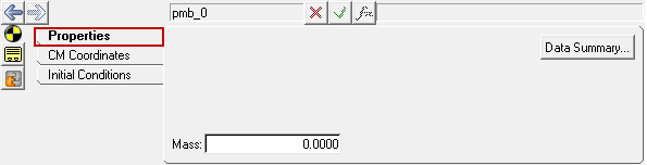
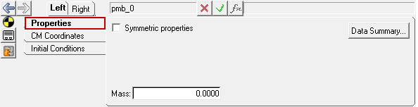
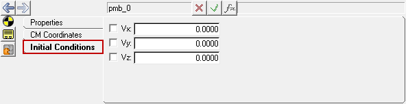
Point Mass Body

The Point Mass body is a reduced version of the six DOF Rigid body.  It only has three translational DOF, therefore the Point Mass body has mass, but no inertia properties.  The position of a point mass is defined by a center of mass point.  By default, the orientation of the point mass is set to be the same as the Global Coordinate System (which never changes during simulation).  The purpose of a Point Mass entity is to add additional representative weight to another body, for example the mass of a driver on a seat.

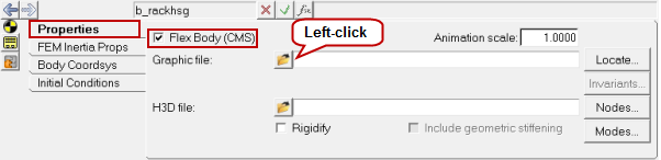
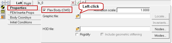
Deformable Body (also known as Flexible Body)

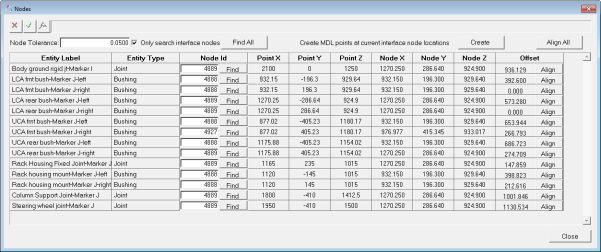
Deformable bodies in multibody systems are those that can be used to model elastic deformation of the bodies of the system.  The Deformable body connects to its neighboring elements/bodies through interface nodes.  The Deformable body consists of reduced stiffness and mass matrices, which can be obtained in various ways.  Two popular methods for the same are: Craig-Bampton Method and Craig-Chang Method.

Properties of a Deformable body are defined using a Flexbody H3D file.  The Flexbody H3D file is created using the Component Mode Systems Method of FE Analysis.  Flexbody H3D files can be created using the Altair OptiStruct FE Solver.  In MotionView, the Utility Flexbody Prep can be used to create Flexbody files from FE models.

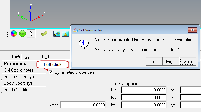
MotionView supports creation of the above types of bodies described as Single body or a Pair body.  For a Pair body, the properties can be made symmetric to the Global Z-X plane (except for a deformable body pair).

Body Properties

Click on each Body type below to view the corresponding properties:

hmtoggle_plus1Rigid Body Properties

Mass and Inertia Properties

The Mass of the Body in the Units of the model and the Inertia tensor of the Body needs to be specified.

Center of Mass Coordinates

The Location of the Center of Mass Marker of the Body.

Inertia Coordinate System

The Location and Orientation of the Inertial Coordinate System of the Body.

Body Coordinate System

The Location and Orientation of the Body Coordinate System of the Body.

Initial Conditions

Translational and Rotational velocity initial conditions for the Body.

hmtoggle_plus1Point Mass Body Properties

Mass

The Mass of the Body in the units of the model.

Center of Mass Coordinates

The Location of the Center of Mass of the Point Mass Body.

Initial Conditions

The Translational velocity initial conditions of the Body.

hmtoggle_plus1Deformable Body Properties

Deformable Body Property and Graphics File

An H3D file containing the Deformation and Graphics information needs to be specified.

The Interface Node List

Resolution of Body Interface nodes with relevant connection Markers.

Body Coordinate System

Location and Orientation of the Body Coordinate System.

Initial Conditions

The Translational and Rotational velocity initial conditions of the Body.

Creating and Editing Bodies

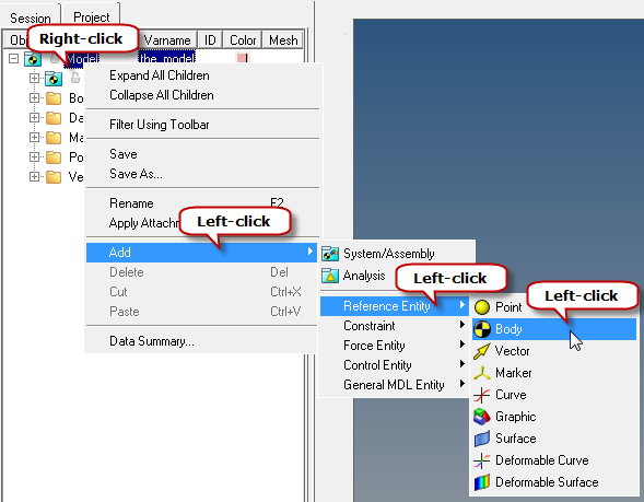
To learn how to add an "Entity" to a model, please see the Entity Manual topic.

hmtoggle_plus1To create/add a Body entity to a model:
1.A Body entity can be added to the model using two different methods:
-From the MotionView Reference Entity toolbar mv_model_reference_toolbar, right-click on the Bodies icon entityMultibodies-24.

OR

-From the Project Browser, right-click on the Model label (or on any System/Analysis of your choice) and select Add > Reference Entity > Body from the context menu.

body_prjct_brwsr_cntxt_menu_mv

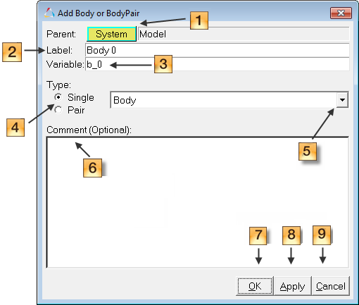
The Add Body or BodyPair dialog is displayed

2.The Add Body or BodyPair dialog can be used specify the System collector, Label, Variable name, and Type of the Body.

add_body_or_bodypair_diagram_mv

3.The System collector located at the top of the dialog (diagram_number_one_mv in the figure above) identifies the System or Container into which the body will be created.  The label "Model" means that the body entity will be created in the Main Model.  You can use this button to change the system into which the body entity will be created/placed.
-To change the system, click the System collector and select the desired system from the Model Tree.
4.Specify a Label for the body (diagram_number_two_mv in the figure above).
5.Specify a Variable name for the body (diagram_number_three_mv in the figure above).

Note - By default variables names of entities in MotionView follow a certain convention.  For example, all Body entities have a variable name starting with “b_”.  This is the recommended convention to follow when building models in MotionView since it has many advantages in model editing and model manipulation.

6.Select a body Type (Single or Pair) (diagram_number_four_mv in the figure above).

Note - A Body entity (like most of the entities that are created in MotionView) can be a Single entity or a Pair entity.  The Pair entities help in creating models which are symmetric about the Z-X Plane of the model. Their properties can also be symmetric about the Z-X Plane (or in other words, the Y property is mirrored).

7.If you want to create a Point Mass Body or an NLFE Body, use the drop-down menu to make your selection (diagram_number_five_mv in the figure above).
8.Optionally, you can also specify a descriptive Comment (diagram_number_six_mv in the figure above) for the body.
9.When you are finished specifying the properties, click OK (diagram_number_seven_mv in the figure above), Apply (diagram_number_eight_mv in the figure above), or Cancel (diagram_number_nine_mv in the figure above).
-Clicking OK will add/create the body entity you described and close the Add Body dialog.
-Clicking Cancel will cancel the body creation operation and close the dialog.
-Clicking Apply will add/create the body; however the dialog will remain open so that more bodies can be added in the same way.
hmtoggle_plus1To edit the properties of a body using the Bodies panel:

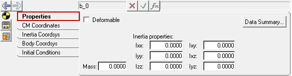
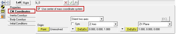
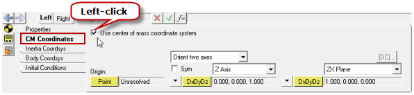
Click on each body type listed below to learn more about using the Bodies panel to edit body properties:
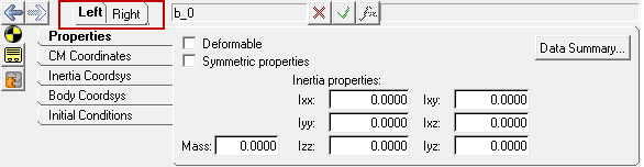
1.The Bodies panel for Single and Pair bodies are shown in the figures below:
-If the selected body is a Single body:  select Properties tab of the body and specify the Mass and Inertia Properties of the body by entering in the values in the appropriate fields.
-If the selected body is a Pair body:  first click on the Left or Right tabs, and then click on the Properties tab to enter the Mass and Inertia Properties of the left or right side of the Pair body.

bodies_panel_rigid_ properties_tab_mv

Mass and Inertia Properties of a Rigid Body - Single

bodies_panel_rigid_ pair_properties_tab_mv

Mass and Inertia Properties of a Rigid Body - Pair

2.To make the body properties symmetric click on the Symmetric properties check box.  Once this option is activated, MotionView will ask you which side of the values of the Pair entity is to be used.  Click the Left or Right buttons to choose the desired side (see the figure below).  Selecting any one side will make values of that side as “master” and the values of the other side will gray out and follow the values on the master side.

bodies_symmetric_props_example_mv

Symmetric Properties (Pair Entity Only)

3.Click on the CM Coordinates tab.
4.Click the Use center of mass coordinate system check box to select a point as the Origin of Center of Mass coordinate for the body.  If a Center of Mass coordinate system is not specified, MotionView assumes that it coincides with the Global Frame of the model.
5.For a Body Pair, a Point Pair should be selected as the CM Coordinates.
6.Click on the Point collector and select the appropriate CM point.  Specify the orientation of the Center of Mass Coordinate System using the Orientation options on this panel. (see the figure below).

bodies_panel_ cm_coordinates_tab_example_mv

Center of Mass Coordinate System Settings - Single

bodies_panel_ cm_coordinates_tab_pair_example_mv

Center of Mass Coordinate System Settings - Pair

7.Optionally, you can specify the Inertia Coordinate System and Body Coordinate System for the body using the Inertia Coordsys and Body Coordsys tabs respectively.  The Inertia Coordinate System is the reference frame with respect to which of the Inertia Properties of the body are specified.

Note - If a unique Inertia Coordinate System is not specified, then the specified Moment of Inertia values are assumed to be defined about the Center of Mass Marker.  If a unique Body Coordinate System is not specified then it is assumed to be at the Global Reference Frame.  This is valid for both Single and Pair body types.

8.Initial Conditions for the body can also be specified if required.  The figure below shows the possible initial conditions that can be applied on the bodies.  The Rotational velocity initial conditions are to be specified in radians per second.

bodies_panel_ initial_conditions_tab_example_mv

Initial Conditions Tab of a Rigid Body - Single

bodies_panel_ initial_conditions_tab_pair_example_mv

Initial Conditions Tab of a Rigid Body - Pair

Note - The translational initial conditions for a body are assumed to be with respect to the Global Reference Frame in absence of a unique VM (Linear Velocity Reference Marker), and the rotational initial conditionals are applied about the Center of Mass Maker in absence of a unique WM (Angular Velocity Reference Marker).

1.The figure below shows the Properties tab for the Points Mass body. Click the CM Coordinates tab to select and specify a Center of Mass Point and Orientation for the Center of Mass Coordinate System.

bodies_panel_point_mass_ properties_tab_mv

Point Mass Body – Mass Property - Single

bodies_panel_point_mass_ pair_properties_tab_mv

Point Mass Body – Mass Property - Pair

2.Optionally, Initial Conditions can also be specified for the Point Mass body.  Since the orientation of a Point Mass body does not change during a simulation, the only applicable Initial Conditions are Linear Velocities specified with respect to the Global Reference Frame (this is shown in the figure below).

bodies_panel_ point_mass_initial_conditions_tab_mv

Initial Conditions for a Point Mass Body - Single

1.The figure below shows the Properties tab for a Deformable body.  Check the Flex Body (CMS) box (formerly the Deformable box) to make the model flexible.  Click on the folder icon to browse and select the Flexbody Property File (H3D file).

bodies_panel_deformable_properties_tab_mv

Properties for a Deformable Body - Single

bodies_panel_deformable_pair_properties_tab_mv

Properties for a Deformable Body - Pair

2.Click the Nodes button on the Properties tab.  The Nodes dialog (as shown in the figure below) is displayed.  This dialog lists the Markers of the entities referring to the Deformable body.  For each marker, a node needs to be specified that will act as an interface between the connecting entities and the Deformable body

nodes_dialog_flexbody

Nodes Dialog

3.From the Nodes dialog, click the Find All button.  MotionView will then find the interface nodes in the Deformable body which are closest to each of the listed markers of the entities connecting the deformable body.  Another option is to click the Find button for the individual markers.  This will look for interface nodes for each marker individually.

Note - The Flexbody H3D file for the Deformable body contains two types of nodes:  Interface nodes and Non-Interface nodes.  The Interface nodes are those which have been selected to be the Interface nodes while creating the Flexbody File.  These are the nodes which connect the Flexbody to the rest of the model.  The check box for Only search interface nodes specifies that only the interface nodes are to be searched.  This ensures that the nodes are found quickly.

4.After the interface nodes are found, the Node IDs will be shown in the Node Id column of the dialog.  The next three columns to the right, Point X, Point Y, and Point Z indicate the coordinate values of the Point that the marker is referring to.  The next three columns, Node X, Node Y, and Node Z indicate the coordinates of the selected interface node.  The last column Offset shows the difference in the point and the node coordinates.
5.If the Offset column shows the offset as 0.000 or 0.001 (this generally happens due to differences in rounding off significant digits) it means that the interface nodes coordinates and the marker origin coordinates are at the same location.

Note - If the offset value is significantly large - a review of the connecting entities, deformable body position, and node coordinate position is recommended.  A large offset value could cause difficulties for the solver or may lead to erroneous results.

6.The Align button at the end of each row can be used to align the point coordinate with that of the node.  This option should be used with significant caution, as it causes the point referenced by the connecting entities to change its position and might affect other entity definitions.
7.The Create button (located in the top right corner of the dialog) can be used to create points at the interface node locations.  This is particularly useful when you need to create points at the interface node location for adding joints or other elements that interact with the Deformable body.
8.Click Close to close the dialog once all operations are done.
9.From the Deformable body panel, click the Modes button (shown in the figure below) to display the Modes dialog.

modes_dialog_example_mv

Deformable Body Modes Dialog

10.Use the drop-down menu to select a desired Deformable body Modal Damping type: Default Damping, CRatio Damping, User Function Damping, and Cratio Expression Damping.

modes_dialog_type_example_mv

Note - Refer to the MotionSolve Reference Guide (Body_Flexible and Reference_Flexdata) for more information about the different types of modal damping.

11.The Modes dialog also shows the modes that belong to the Deformable body and gives information about the Model frequency.  By default, the first six Modes whose frequencies are zero (or close to zero) are unselected.  This is because the rigid modes of the Deformable body should be used when solving the model in MotionSolve.  Further you can unselect any mode that you think should not be included in the model.  This should be done by advanced users only!
NoteProperties of several bodies can be edited simultaneously using the Data Summary dialog.

Creating Bodies using MDL and Tcl

Bodies can also be created in the following ways in MotionView:

Using MDL statements in an MDL file
Using the HyperWorks Tcl API
hmtoggle_plus1To create bodies using MDL Statements in an MDL File:

MotionView models are saved as Model Definition Language (MDL) statements in text files.  MDL is a text based language and can be easily created using any Text Editor.

Each type of body (listed below) needs an appropriate set of MDL statements for proper definition in the model.

mv_entity_topology_prop_data_example_mv

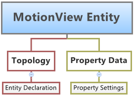
MDL Entity Definition

The definition of every entity that is created in MotionView is divided into two parts: Topology and Property.  Therefore in most cases, two or more statements must be used to create an entity using MDL.

The following eight body types can be created using MDL:

A single rigid body can be added to a model by adding the following two statements:

1.*Body() - adds a body to a model.

Syntax: *Body(body_name, "body_label", [cm_origin], [im_origin], [lprf_origin], [vm_marker], [wm_marker])

2.*SetBodyInertia() - specifies the properties of a body (namely, mass, and inertia properties).

Syntax: *SetBodyInertia(body_name, mass, ixx, iyy, izz, ixy, ixz, iyz)

Note - Extended definitions for *Body() and *SetBodyInertia() can be found in the HyperWorks Desktop Reference Guide.

An asymmetric body pair can be added to the model with the following two statements:

1.*BodyPair() - adds the body pair topology to the model.

Syntax: *BodyPair(body_name, "body_label", [cm_origin], [im_origin], [lprf_origin], [vm_marker], [wm_marker])

2.*SetBodyInertia() - specifies the properties for the asymmetric body pair.

Syntax: *SetBodyInertia(body_name, ,mass_l, ixx_l, iyy_l, izz_l, ixy_l, ixz_l, iyz_l, mass_r, ixx_r, iyy_r, izz_r, ixy_r, ixz_r, iyz_r)

Note - Extended definitions for *BodyPair() and *SetBodyInertia() can be found in the HyperWorks Desktop Reference Guide.

The topology statement for the symmetric body pair is the same as the asymmetric body pair.  The only difference is in the *SetBodyInertia() statement which will be as shown below:

1.*SetBodyInertia() - specifies the properties for the symmetric body pair.

Syntax: *SetBodyInertia(body_name, LEFT|RIGHT, mass, ixx, iyy, izz, ixy, ixz, iyz)

Note - An extended definition for *SetBodyInertia() can be found in the HyperWorks Desktop Reference Guide.

A single point mass body will need two MDL statements for topology and property definition:

1.*PointmassBody() - defines the topology.

Syntax: *PointmassBody(pmb_name, "pmb_label", [cm_origin], [lprf_origin])

2.*SetPointmassBody() - defines the mass property of the point mass body.

Syntax: *SetPointmassBody(pmb_name, mass)

Note - Extended definitions for *PointmassBody and *SetPointmassBody() can be found in the HyperWorks Desktop Reference Guide.

An asymmetric point pair mass body will need to two MDL statements for topology and property definition:

1.*PointmassBodyPair() - defines the topology.

Syntax: *PointmassBodyPair(pmb_name, "pmb_label", [cm_origin], [lprf_origin])

2.*SetPointmassBody() - defines the property data definition.

Syntax: *SetPointmassBody(pmb_name, mass_l, mass_r)

The topology statement for a symmetric point pair mass body is the same as it is for the asymmetric point mass body, however the only difference will be in the property data definition (shown below):

1.*SetPointmassBody() - defines the property data definition of a symmetric point pair mass body.

Syntax: *SetPointmassBody(pmb_name, LEFT|RIGHT, mass)

Creating flexible bodies using MDL statements is a multi-step process:

1.Create a Rigid body.
2.Set the Compliance State of the Rigid body to Deformable using *SetFlexbodyComplianceState.
3.Set the properties of the now Deformable body using the following:
a.*SetFlexbodySolverData
b.*SetFlexbodyNode
c.*SetFlexbodyDamping
d.*SetFlexbodyInvariants
e.*SetFlexbodyModes
f.*SetFlexbodyDmodes
g.*SetFlexbodyVmodes
h.*SetFlexbodyMexact

When it comes to flexible bodies there are no separate statements for single and pair flexible bodies.  The steps to be followed when defining flexible pair bodies will be that first Rigid pair bodies have to be created and each side of the pair can be made flexible individually.  To define the properties of the flexible pair bodies, individual property statements that set the properties of the left and right side separately are used.

In most cases, the property statements a. and b. (listed above) will be the only properties that need to be set.  Property settings c. to h. will need to be used only for advanced control of the flexbody properties.  Also, the statements in blue (above) are those that are applicable to MotionSolve, ADAMS, and ABAQUS, while those that are in red are applicable only to the ADAMS solver.  The one statement that is in dark red is applicable to MotionSolve and ADAMS, but not to ABAQUS.

The MDL syntax and argument descriptions for all of the above statements are provided below:

1.*SetFlexbodyComplianceState() - sets the state of a body to flexible, as well as the source of the matrix file that describes the flexbody.

Syntax: *SetFlexbodyComplianceState(body_name, RIGID|DEFORMABLE)

2.*SetFlexbodySolverData() - sets the flexbody solver data.

Syntax: *SetFlexbodySolverData(body_name, SOLVER_NAME, Input_Type, graphic_file, func_file1, func_file2)

3.*SetFlexbodyNode() - sets the pairing of a flexbody node and the part of the MDL model to which it is being attached.

Syntax: *SetFlexbodyNode(object_name, I_MARKER|J_MARKER|BLANK, node_id)

4.*SetFlexbodyDamping() - sets the damping for a flexbody entity.

Syntax: *SetFlexbodyDamping(object_name, SOLVER_NAME, damping_type, value1, value2, ...valueN)

5.*SetFlexbodyInvariants() - sets the nine boolean states for the flexbody invariants.

Syntax: *SetFlexbodyInvariants(object_name, SOLVER_NAME, "TTTTFTTTT")

6.*SetFlexbodyModes() - identifies which modes are included when MotionView generates the flexbody matrix file for the solver.

Syntax: *SetFlexbodyModes(body_name, SOLVER_NAME, mode1, mode2, ...modeN)

7.*SetFlexbodyDmodes() - sets the initial value of the modal coordinates of a flexbody.

Syntax: *SetFlexbodyDmodes(body_name, SOLVER_NAME, damping_type, value1, value2...valueN)

8.*SetFlexbodyVmodes() - sets the initial values of the velocity of the flexbody modal coordinates.

Syntax: *SetFlexbodyVmodes(body_name, SOLVER_NAME, v1, v2, ...vn )

9.*SetFlexbodyMexact() - specifies which modal body coordinates the solver should not change during initial condition calculation.

Syntax: *SetFlexbodyMexact(body_name, SOLVER_NAME, m1, m2, ...mN)

hmtoggle_plus1To create Bodies using the HyperWorks Tcl API:

A body can be added to the model using the HyperWorks TCL API.  The benefit of using this method is that it facilitates automated model building.  If the model is of a known configuration then precious time can be saved by automating the model building process by writing a TCL script to do all, or a portion, of the model building.  There are two commands which can be used to add or edit bodies in MotionView:

Syntax

mdlIObject_handle InterpretEntity new_handle keyword varname label

Description

This command adds a new entity using the MDL statements keyword, variable name, and label.


Note - You can specify the new entity's type, variable name, and label, as well as other topology arguments.

new_handle

The handle for the new entity.

keyword

The new entity's MDL statement keyword.

varname

The new entity's variable name.

label

The new entity's label.

Syntax

mdlIObject_handle InterpretSet keyword tokens

Description

This command adds a new set statement to the system.


Note - You must specify all tokens for the requested MDL set statement.

keyword

The new entity's MDL statement keyword.

tokens

The remaining tokens for the corresponding MDL statement.

These two commands go hand in hand and will create a Body entity with the variable and label specified in them.

Note - Extended definitions for InterpretEntity and InterpretSet can be found in the HyperWorks Desktop Reference Guide.

For every entity that is to be added to the model, four lines of TCL code are necessary:

1.The InterpretEntity [1] command line which adds the entity to the model.
2.The InterpretSet [2] command line which is used to define the properties of the entity.
3.The Evaluate [3] command line which evaluates and update the properties defined using the InterpretSet command line.
4.The entity_handle ReleaseHandle [4] command line which releases the entity handle obtained using the InterpretEntity command line.

Note - For editing an existing entity, only command lines 2 and 3 (above) are necessary.

Syntax for Creating a Single Body:

model_handle InterpretEntity body_handle Body b_004 "\"New Single Body 2\""; --[1]

model_handle InterpretSet SetBody b_004 10 1E4 1E4 1E4 1000 1000 1000; --[2]

model_handle InterpretSet SetBodyICFlag b_004 "true" "false" "false" "true" "false" "false";

model_handle InterpretSet SetBodyIC b_004 100 "" "" 10;

model_handle Evaluate; --[3]

body_handle ReleaseHandle; --[4]

Syntax for Creating a Asymmetric Body Pair:

model_handle InterpretEntity body_handle BodyPair b_005 "\"New Asymm Pair Body 2\"";

model_handle InterpretSet SetBody b_005 "" 10 1E4 1E4 1E4 1000 1000 1000 10 1E4 1E4 1E4 1000 1000 1000;

model_handle Evaluate;

body_handle ReleaseHandle;

Syntax for Creating a Symmetric Body Pair:

model_handle InterpretEntity body_handle BodyPair b_006 "\"New Symm Pair Body 2\"";

model_handle InterpretSet SetBody b_006 "LEFT" 10 1E4 1E4 1E4 1000 1000 1000;

model_handle Evaluate;

body_handle ReleaseHandle;

Tcl commands can be executed one by one using the Command Window (View > Command Window), or they can be part of a Tcl script which can be executed also from File > Run > Tcl/Tk Script menu option.  To learn this method of model building in more detail please refer to tutorial MV-1040: Model Building Using Tcl.

Body Entity in the MotionSolve XML Format

When the Body entity gets exported to MotionSolve, it is exported into the XML Model statements listed in the table below:

ID

Body Type

XML Statement

1

Rigid Body

Body_Rigid

2

Point Mass Body

Body_Point

3

Deformable Body

Body_Flexible and Reference_Flexdata

Click on the body type below to view the corresponding syntax for each XML statement:

hmtoggle_plus1Rigid Body XML Statement

Syntax:

<Body_Rigid>

    id                  = "integer"

 [  cg_id               = "integer"  ]

 [  im_id               = "integer" ]

 [  isground            = { "TRUE" | "FALSE" } ]

 [  mass                = "real" ]

 [  inertia_xx          = "real"

    inertia_yy          = "real"

    inertia_zz          = "real"

    inertia_xy          = "real"

    inertia_yz          = "real"

    inertia_xz          = "real" ]

 [  v_ic_x              = "real" ]

 [  v_ic_y              = "real" ]

 [  v_ic_z              = "real" ]

 [  w_ic_x              = "real"

    w_ic_y              = "real"

    w_ic_z              = "real" ]

 [  v_ic_x_flag         = { "TRUE" | "FALSE" } ]

 [  v_ic_y_flag         = { "TRUE" | "FALSE" } ]

 [  v_ic_z_flag         = { "TRUE" | "FALSE" } ]

 [  w_ic_flag           = { "TRUE" | "FALSE" } ]

</Body_Rigid >

hmtoggle_plus1Point Mass Body XML Statement

Syntax:

<Body_Point>

   id                  = "integer"

   cg_id               = "integer"

   mass                = "real"

   v_ic_x              = "real"

   v_ic_y              = "real"

   v_ic_z              = "real"

   v_ic_x_flag         = { "TRUE" | "FALSE" }

   v_ic_y_flag         = { "TRUE" | "FALSE" }

   v_ic_z_flag         = { "TRUE" | "FALSE" }

</Body_Point>

hmtoggle_plus1Deformable Body XML Statement

In the case of the Deformable body the body definition is split into two XML statements:

Syntax:

<Body_Flexible

    id                  = "integer"

    label               = “Name of the Flex Body”

    lprf_id             = "integer"

    mass                = “integer”

    inertia_xx          = “interger”

    inertia_yy          = “interger”

    intertia_zz         = “integer”

    intertia_xy         = “interger”

    inertia_yz          = “interger”

    intertia_xz         = “interger”

    cm_x                = “interger”

    cm_y                = “interger”

    cm_z                = “interger”

    h3d_file            = ”valid_path_name”

    is_user_damp        = “TRUE”

    cdamp_expr          = “motionsolve_expression”

    flexdata_id         = "integer"

    animation_scale     = "real"

 {

   [

   |

     usrsub_dll_name     = "valid_path_name"

     usrsub_param_string = "USER( [[par_1 [, ...][,par_n]] )"

     usrsub_fnc_name     = "custom_fnc_name" >

   |

     script_name         = valid_path_name

     interpreter         = "PYTHON" | "MATLAB"

     usrsub_param_string = "USER( [[par_1 [, ...][,par_n]] )"

     usrsub_fnc_name     = "custom_fnc_name" >

   ]

 }

 [   rigidified          = { "TRUE" | "FALSE" } ]

 [   v_ic_x              = "real" ]

 [   v_ic_y              = "real" ]

 [   v_ic_z              = "real" ]

 [   w_ic_x              = "real"

     w_ic_y              = "real"

     w_ic_z              = "real" ]

 [   v_ic_x_flag         = { "TRUE" | "FALSE" } ]

 [   v_ic_y_flag         = { "TRUE" | "FALSE" } ]

 [   v_ic_z_flag         = { "TRUE" | "FALSE" } ]

 [   w_ic_flag           = { "TRUE" | "FALSE" } ]

/>

Syntax:

<Reference_FlexData

   id                  = "integer"

   num_nodes           = "integer"

   num_sel_modes       = "integer"

   num_sel_nodes       = "integer"

Frequency and damping data for each selected mode:

   <ModeData>

      !ID    Frequency   Eigenvalue    Damping

     integer   real       real         real

      ...      ...        ...          ...

      ...      ...        ...          ...

     integer   real       real         real

   </ModeData>

Coordinates for nodes in the FE model that are attachment points in MMBS model:

   <NodeData>

      !ID       X          Y            Z

     integer   real       real         real

      ...      ...        ...          ...

      ...      ...        ...          ...

     integer   real       real         real

Mode participation at each node:

     !-- Mode Shape Date

     real     real      real      real      real      real

     ...      ...       ...       ...       ...       ...

     ...      ...       ...       ...       ...       ...

     real     real      real      real      real      real

   </NodeData>

Inertia invariants for structural system:

</Reference_FlexData>

Note - The Body_Flexible statement refers to the Reference_Flexdata statement.

To understand the complete syntax of the MotionSolve XML statements please refer to the MotionSolve Reference Guide.

Initial Condition Settings

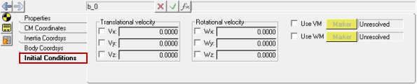
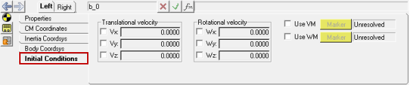
Initial conditions can be specified for Rigid and Point Mass bodies located in a model.

hmtoggle_plus1To specify initial conditions settings for a Rigid Body:

Initial conditions can be specified to the Rigid bodies in a particular model in two ways:

A common initial conditions setting for all the bodies in the model or a selected system.
An individual initial conditions setting for each body (single and pair).

In either case mentioned above the initial conditions need to be set using two statements: an initial condition settings flag and then the initial condition value.

Syntax: *SetBodyIC(sys_name|BODIES, vx, vy, vz, wx, wy, wz)

*SetBodyICFlag(sys_name/BODIES, vx_f, vy_f, vz_f,
wx_f, wy_f, wz_f)

Syntax: *SetBodyIC(body_name, vx, vy, vz)

*SetBodyICFlag(body_name, vx_f, vy_f, vz_f)

Syntax: *SetBodyIC(body_name, vx_l, vy_l, vz_l, vx_r, vy_r, vz_r)

*SetBodyICFlag(body_name, vx_lf, vy_lf, vz_lf, vx_rf,
vy_rf, vz_rf)

hmtoggle_plus1To specify initial conditions settings for a Point Mass Body:

Initial conditions can be specified for the Point Mass bodies in a particular model in two ways:

A common initial conditions setting for all of the Point Mass bodies.
An individual initial conditions setting for each Point Mass body (single and pair).

In either case mentioned above the initial conditions need to be set using two statements: an initial condition settings flag and then the initial condition value.

Syntax: *SetPointmassBodyIC(sys_name|BODIES, vx, vy, vz)

*SetPointmassBodyICFlag(sys_name|BODIES, vx_f, vy_f, vz_f)

Syntax: *SetPointmassBodyIC(pmb_name, vx, vy, vz)

*SetPointmassBodyICFlag(pmb_name, vx_f, vy_f, vz_f)

Syntax: *SetPointmassBodyIC(pmb_name, vx_l, vy_l, vz_l, vx_r, vy_r, vz_r)

*SetPointmassBodyICFlag(pmb_name, vx_lf, vy_lf, vz_lf, vx_rf, vy_rf, vz_rf)

Example Models

The following example files are available:

hmtoggle_plus1Bodies.mdl

The example below shows the different types of body entities created in a model. It also shows a body that has been parameterized.

*BeginMDL( the_model, "Model" )


 *StandardInclude(FILE)

 *SetCurrentSolverMode(MotionSolve)

 *Point( p_001, "New Single Point" )

 *PointPair( p_002, "New Asymm Pair Point" )

 *PointPair( p_003, "New Symm Pair Point" )

 *Body( b_001, "New Single Body", p_001, , , Global_Frame, Global_Frame )

 *BodyPair( b_002, "New Asymm Body Pair", p_002, , , ,  )

 *BodyPair( b_003, "New Symm Body Pair", p_003, , , ,  )

 *Point( p_004, "New Single Point 2" )

 *PointPair( p_005, "New Asymm Pair Point 2" )

 *PointPair( p_006, "New Symm Pair Point 2" )

 *Body( b_004, "New Single Body 2", , , , ,  )

 *BodyPair( b_005, "New Asymm Pair Body 2", , , , ,  )

 *BodyPair( b_006, "New Symm Pair Body 2", , , , ,  )

 *PointMassBody( pmb_0, "Point Mass Body 0", p_001,  )

 *SetPoint( p_001, 100, 20, 20 )

 *SetPoint( p_002, , 100, 22, 20, 100, -22, 20 )

 *SetPoint( p_003, LEFT, 100, 25, 20 )

 *SetBodyInertia( b_001, 10, 1E4, 1E4, 1E4, 1000, 1000, 1000 )

 *SetBodyInertia( b_002, , 10, 1E4, 1E4, 1E4, 1000, 1000, 1000, 10, 1E4, 1E4, 1E4, 1000, 1000, 1000 )

 *SetBodyInertia( b_003, LEFT, 10, 1E4, 1E4, 1E4, 1000, 1000, 1000 )

 *SetPoint( p_004, 200, 20, 20 )

 *SetPoint( p_005, , 200, 30, 20, 200, -30, 20 )

 *SetPoint( p_006, LEFT, 200, 40, 20 )

 *SetBodyInertia( b_004, 10, 1E4, 1E4, 1E4, 1000, 1000, 1000 )

 *SetBodyInertia( b_005, , 10, 1E4, 1E4, 1E4, 1000, 1000, 1000

                         , 10, 1E4, 1E4, 1E4, 1000, 1000, 1000 )

 *SetBodyInertia( b_006, LEFT, 10, 1E4, 1E4, 1E4, 1000, 1000, 1000 )

 *SetBodyICFlag( b_001, true, false, false, true, false, false )

 *SetBodyIC( b_001, 100, , , 10 )

 *SetPointMassBody( pmb_0, 200 )

 *SetPointMassBodyICFlag( pmb_0, true )

 *SetPointMassBodyIC( pmb_0, 30 )

 *Set( pmb_0.usecm, true )

 *SetOrientation( pmb_0.cm, TWOAXES, ZX, DXDYDZ, , , , DXDYDZ )

 *Set( b_001.useim, false )

 *Set( b_001.uselprf, false )

 *SetActiveAnalysis( NONE )

*EndMDL()

hmtoggle_plus1Bodies.tcl

The example below shows the different types bodies created using Tcl.

## TCL Macro to Create/Edit Bodies using

## 1. AppendMDL

## 2. InterpretEntity and InterpretSet


hwi OpenStack

hwi GetSessionHandle session_handle

session_handle GetProjectHandle project_handle

project_handle GetPageHandle page_handle [project_handle GetActivePage]

page_handle GetWindowHandle window_handle [page_handle GetActiveWindow]

window_handle GetClientHandle client_handle

client_handle GetModelHandle model_handle


## Create Bodies using AppendMDL

model_handle AppendMdl "*Point(p_001, \"New Single Point\")"

model_handle AppendMdl "*SetPoint(p_001, 100, 20, 20)"


model_handle AppendMdl "*PointPair(p_002, \"New Asymm Pair Point\")"

model_handle AppendMdl "*SetPoint(p_002,, 100, 22, 20, 100, -22, 20)"


model_handle AppendMdl "*PointPair(p_003, \"New Symm Pair Point\")"

model_handle AppendMdl "*SetPoint(p_003, LEFT, 100, 25, 20)"


model_handle AppendMdl "*Body(b_001, \"New Single Body\", p_001)";

model_handle AppendMdl "*SetBody(b_001, 10, 1E4, 1E4, 1E4, 1000, 1000, 1000)";


model_handle AppendMdl "*BodyPair(b_002, \"New Asymm Body Pair\", p_002)";

model_handle AppendMdl "*SetBody(b_002, ,10, 1E4, 1E4, 1E4, 1000, 1000, 1000, 10, 1E4, 1E4, 1E4, 1000, 1000, 1000)";


model_handle AppendMdl "*BodyPair(b_003, \"New Symm Body Pair\", p_003)";

model_handle AppendMdl "*SetBody(b_003, LEFT,10, 1E4, 1E4, 1E4, 1000, 1000, 1000)";


## Create Point using InterpreEntity

## mdlIObject_handle InterpretEntity new_handle keyword varname label

set point_coords { 200 20 20 };


model_handle InterpretEntity point_handle Point p_004 "\"New Single Point 2\"";

model_handle InterpretSet SetPoint p_004 200 20 20;

model_handle Evaluate;

point_handle ReleaseHandle;


model_handle InterpretEntity point_handle PointPair p_005 "\"New Asymm Pair Point 2\"";

model_handle InterpretSet SetPoint p_005 "" 200 30 20 200 -30 20;

model_handle Evaluate;

point_handle ReleaseHandle;


model_handle InterpretEntity point_handle PointPair p_006 "\"New Symm Pair Point 2\"";

model_handle InterpretSet SetPoint p_006 "LEFT" 200 40 20;

model_handle Evaluate;

point_handle ReleaseHandle;


model_handle InterpretEntity body_handle Body b_004 "\"New Single Body 2\"";

model_handle InterpretSet SetBody b_004 10 1E4 1E4 1E4 1000 1000 1000;

model_handle InterpretSet SetBodyICFlag b_004 "true" "false" "false" "true" "false" "false";

model_handle InterpretSet SetBodyIC b_004 100 "" "" 10;

model_handle Evaluate;

body_handle ReleaseHandle;


model_handle InterpretEntity body_handle BodyPair b_005 "\"New Asymm Pair Body 2\"";

model_handle InterpretSet SetBody b_005 "" 10 1E4 1E4 1E4 1000 1000 1000 10 1E4 1E4 1E4 1000 1000 1000;

model_handle Evaluate;

body_handle ReleaseHandle;


model_handle InterpretEntity body_handle BodyPair b_006 "\"New Symm Pair Body 2\"";

model_handle InterpretSet SetBody b_006 "LEFT" 10 1E4 1E4 1E4 1000 1000 1000;

model_handle Evaluate;

body_handle ReleaseHandle;


model_handle ReleaseHandle;

client_handle ReleaseHandle;

window_handle ReleaseHandle;

page_handle ReleaseHandle;

project_handle ReleaseHandle;

session_handle ReleaseHandle;

hwi CloseStack

See Also:

Bodies Panel

Adding and Removing Entities

*Body() (MDL Model Statement)

mdlIObject InterpretEntity (Tcl Command)

mdlIObject InterpretSet (Tcl Command)

MV-1040: Model Building Using Tcl