MotionView User's Guide

Points

Points

Previous topic Next topic Expand/collapse all hidden text  

Points

Previous topic Next topic JavaScript is required for expanding text JavaScript is required for the print function  

This topic describes the Point entity in MotionView and shows the various usage, creation, and editing methods.

Theory/Background

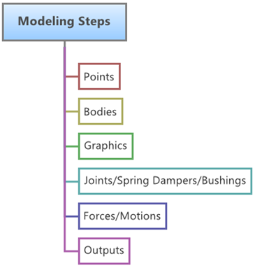
The figure below shows the most commonly used modeling elements in MotionView.  Points are one of the fundamental construction elements for multibody models built in MotionView.  Also, almost all the entities that can be created in MotionView need to use points either for defining their location or orientation.  Therefore the creation of points is an important task in model building within MotionView.

mv_modeling_steps_diagram

In MotionView you can create the following types of points:

Single Point
Point Pair (Asymmetric or Symmetric)

Point Entity Properties

A Point entity is defined by its three Cartesian coordinates X, Y and Z.

point_entity_properties_diagram_mv

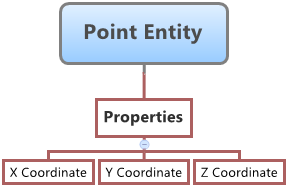
Point Entity – Properties Map

A Point entity (like most of the entities that are created in MotionView) can be a Single entity or a Pair entity.  The Pair entities help in creating models which are symmetric about the Z-X Plane of the model.  Asymmetry or Symmetry of the points can be decided or specified when editing the created point.

Creating and Editing Points

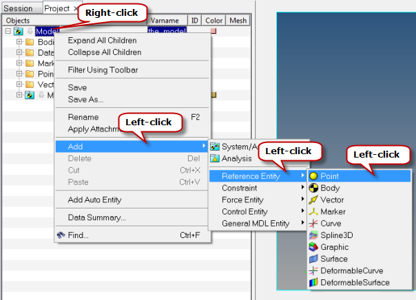
To learn how to add an "Entity" to a model, please see the Entity Manual topic.

hmtoggle_plus1To create/add a Point entity to a model:
1.A Point entity can be added to the model using two different methods:
-From the MotionView Reference Entity toolbar, right-click on the Points icon point-24

point_panel_icon_rght_click_mv

OR

-From the Project Browser, right-click on the Model label (or on any System/Analysis of your choice) and select Add > Reference Entity > Point from the context menu.

point_prjct_brwsr_cntxt_menu_mv

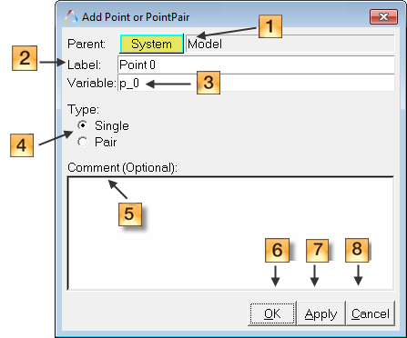
The Add Point or PointPair dialog is displayed

2.The Add Point or PointPair dialog can be used specify the System collector, Label, Variable name, and Type of the Point.

add_point_or_pointpair_diagram_mv

3.The System collector located at the top of the dialog (diagram_number_one_mv in the figure below) identifies the system or container into which the point will be created. The label "Model" means that the point entity will be created in the Main Model. You can use this button to change the system into which the point entity will be created/placed.
4.To change the system, click the System collector and select the desired system from the Model Tree.

By default, the points are created in a model level Cartesian coordinate system called the Global Reference Frame, and this is the only coordinate system currently available in MotionView.

5.Specify a Label for the point (diagram_number_two_mv in the figure above).
6.Specify a Variable name for the point (diagram_number_three_mv in the figure above).

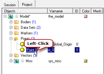
Note - By default, variables names of entities in MotionView follow a certain convention.  For example, all point entities have a variable name starting with “p_”.  This is the recommended convention to follow when building models in MotionView since it has many advantages in model editing and model manipulation.

7.Select a point Type: Single or Pair (diagram_number_four_mv in the figure above). This selection decides whether the point is going to be a single point or a point pair.

Note - A point entity, like most of the entities that are created in MotionView, can be a single entity or a pair entity.  Pair entities help in creating models which are symmetric about the Z-X Plane of the model.  Their properties can also be symmetric about the Z-X Plane (in other words, the Y property is mirrored).  Asymmetry or symmetry of the points can be decided or specified when editing the created point.

8.Optionally, you can specify a descriptive Comment (diagram_number_five_mv in Figure 2 above) for the point.
9.When you are finished specifying the properties, click OK (diagram_number_six_mv in the figure above), or Apply (diagram_number_seven_mv in the figure above), or Cancel (diagram_number_eight_mv in the figure above).
-Clicking OK will add/create the point entity you described and close the Add Point dialog.
-Clicking Cancel will cancel the point creation operation and close the dialog.
-Clicking Apply will add/create the point; however the dialog will remain open so that more points can be added in the same way.
hmtoggle_plus1To create points using Point Creation Macros:
1.From the Macros menu, select the Create>at Arc Center option.

macros_menu_create_points_btwn_points_mv

2.The Create Points at Arc Center macro provides four methods of creating points between existing points of a MotionView model. These points can be used for model construction purposes.

macros_menu_create_btwn_points

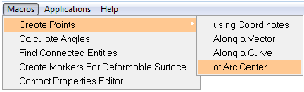
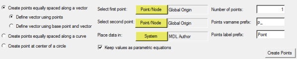
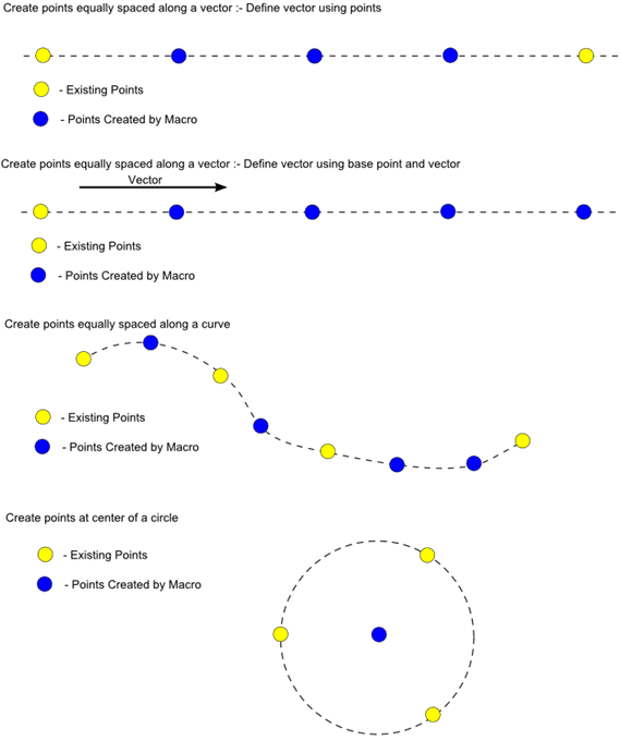
Create Points Between Points Macro Panel

A pictorial representation of the functionality of each of the four point creation macro methods is shown in the image below:

point_creation_macro_diagram_mv

3.Select the appropriate creation method.
4.Select the required points.
5.Specify the desired prefix for Label and Variable names.
6.Click Create Points.

Note - The current Create Points at Arc Center macro supports the creation of single type points only!  Point pair entities cannot be created using this method.

hmtoggle_plus1To edit a point using the Project Browser:
1.To edit a previously created point, select the point entity that needs to be edited in the Project Browser by left-clicking on the point label.

point_selection_prjct_brwsr_mv

The Points panel for the selected point is automatically displayed.

2.The coordinates of the point can be edited as outlined in the section below.

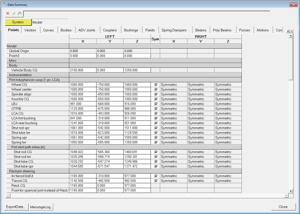
Note - It is possible to edit multiple points from a single interface called the Data Summary (see below).

hmtoggle_plus1To edit the properties of a point using the Points panel:

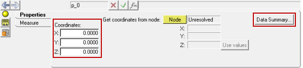
A point is primarily defined by its Cartesian coordinates in the X, Y, and Z axes.

points_panel_diagram_mv

Points Panel with the X, Y, and Z Coordinates fields and Data Summary button highlighted

1.To specify the X, Y, and Z coordinate values:  click in the fields for X, Y, or Z coordinates (highlighted in the image above) and type in a value for each coordinate.
2.Alternatively, the point’s coordinates can be extracted from the node of a File Graphic defined using an H3D File that exists in the model and is visible in the graphics area. Click on the Node collector and then left-click on any graphic node in the graphics area.

point_selection_in_graphics_area_mv

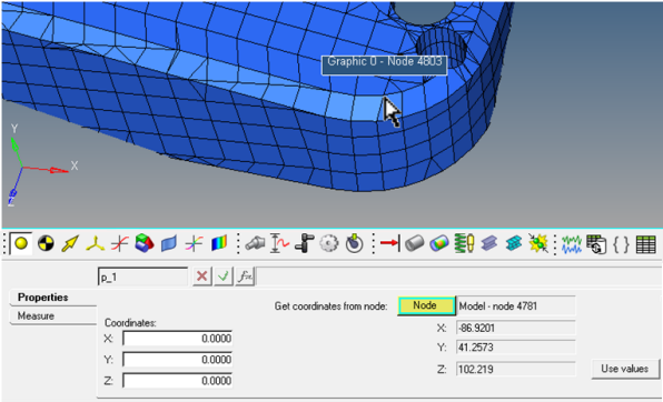
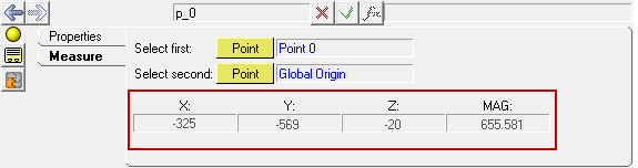
Extracting Point Coordinates from Nodes of File Graphics

3.The coordinates of the node are extracted and displayed in the panel (see the figure above).
4.Click on the Use values button to use the shown values as the coordinates of the point.
5.The Measure tab on the Points panel (shown in the figure below) is used to measure the distance between any two points in the model.

points_panel_measure_tab_xyz_mag_mv

6.Click on the Measure tab, pick the two points for which the distance is to be calculated and the panel will show the distance between the two points in the highlighted area on the panel.
hmtoggle_plus1To edit multiple points using Data Summary:
1.From the Points panel, click the Data Summary button to access the Data Summary dialog.

OR

From the Model menu, select Data Summary.

2.Click inside the text box of the desired point and edit the value.

points_data_summary_dialog_mv

Data Summary Dialog

3.Click Close.

Creating and Editing Points using MDL and Tcl

Points can also be created in the following ways in MotionView:

Using MDL statements in an MDL file
Using the HyperWorks Tcl API
hmtoggle_plus1To create points using MDL Statements in an MDL File:

MotionView models are saved as Model Definition Language (MDL) statements in text files.  MDL is a text based language which can easily be created using any Text Editor.

A point can be added to a model by adding the following two statements that define a point to the MDL file of a model:

1.*Point() - adds a point to a model.

Syntax: *Point(point_name, "point_label", [point_num])

2.*SetPoint() - specifies the coordinates of a point.

Syntax: *SetPoint(point_name, x, y, z)

Note - Extended definitions of *Point() and *SetPoint() - single point can be found in the HyperWorks Desktop Reference Guide.

A point pair can be added to a model by adding the following two statements that define a point to the MDL file of a model:

1.*PointPair() - adds a point pair to a model.

Syntax: *PointPair(point_name, "point_label", [point_num_1], [point_num_2])

2.*SetPoint() - specifies the coordinates of a point pair:

Asymmetric Point Pair

Syntax: *SetPoint(point_name, , x_l, y_l, z_l, x_r, y_r, z_r)

Symmetric Point Pair

Syntax: *SetPoint(point_name, LEFT|RIGHT, x, y, z)

Note - Extended definitions of *Point(), *SetPoint() - asymmetric point pair, and *SetPoint() - symmetric point pair can be found in the HyperWorks Desktop Reference Guide.

hmtoggle_plus1To edit points using MDL Statements in an MDL File:

Once a point entity has been create by any of the methods mentioned above and the model is saved as an MDL file, the points created can be edited by making changes to the MDL statements corresponding to the entity.  As discussed above the properties of a point entity are the point coordinates.  This is set by the MDL statement starting with *SetPoint().

1.Open the saved MDL file in a Text Editor and search for the point to be edited by its variable name or label.
2.The search will show the statement *SetPoint() where the new coordinates of the point can be specified.
3.The same approach works for both single and pair entities.
4.Once the point has been edited, save the MDL file and re-load the file into MotionView.
5.The edited points will be seen in their new positions in the graphics area.
hmtoggle_plus1To create and edit points using the HyperWorks Tcl API:

A point can be added to the model using the HyperWorks TCL API.  The benefit of using this method is that it facilitates automated model building.  If the model is of a known configuration then time can be saved by automating the model building process by writing a TCL script to do all, or a portion, of the model building.  There are two commands which can be used to add or edit points:

Syntax

mdlIObject_handle InterpretEntity new_handle keyword varname label

Description

This command adds a new entity using the MDL statements keyword, variable name, and label.


Note - You can specify the new entity's type, variable name, and label, as well as other topology arguments.

Syntax

mdlIObject_handle InterpretSet keyword tokens

Description

This command adds a new set statement to the system.


Note - You must specify all tokens for the requested MDL set statement.

These two commands go hand in hand and will create a Point entity with the variable and label specified in them.

Note - Extended definitions of InterpretEntity and InterpretSet can be found in the HyperWorks Desktop Reference Guide.

For every entity that is to be added to the model, four lines of TCL code are necessary:

1.The InterpretEntity [1] command line which adds the entity to the model.
2.The InterpretSet [2] command line which is used to define the properties of the entity.
3.The Evaluate [3] command line which evaluates and update the properties defined using the InterpretSet command line.
4.The entity_handle ReleaseHandle [4] command line which releases the entity handle obtained using the InterpretEntity command line.

Note - For editing an existing entity, only command lines 2 and 3 (above) are necessary.

Syntax for Creating a Single Point:

model_handle InterpretEntity point_handle Point p_004 "\"New Single Point 2\"";                                                 ---[1]

model_handle InterpretSet SetPoint p_004 200 20 20;         ---[2]

model_handle Evaluate;                                      ---[3]

point_handle ReleaseHandle;                                 ---[4]

Syntax for Creating an Asymmetric Point Pair:

model_handle InterpretEntity point_handle PointPair p_005 "\"New Asymm Pair Point 2\"";

model_handle InterpretSet SetPoint p_005 "" 200 30 20 200 -30 20;

model_handle Evaluate;

point_handle ReleaseHandle;

Syntax for Creating a Symmetric Point Pair:

model_handle InterpretEntity point_handle PointPair p_006 "\"New Symm Pair Point 2\"";

model_handle InterpretSet SetPoint p_006 "LEFT" 200 40 20;

model_handle Evaluate;

point_handle ReleaseHandle;

TCL commands can be executed one by one using the Command Window (View > Command Window), or they can be part of a TCL script which can be executed also from File > Run > Tcl/Tk Script menu option.  To learn this method of model building in more detail please refer to tutorial MV-1040: Model Building Using TCL.

Example Model Files

The following example files are available in the installation:

hmtoggle_plus1Points.mdl

The example below shows the different types of point entities created in a model.  It also shows a point that has been parameterized.

*BeginMDL( the_model, "Model", "11.0.0.130-HWDesktop" )


 *StandardInclude(FILE)

 *SetCurrentSolverMode(MotionSolve)

 *Point( p_001, "New Single Point" )

 *SetPoint( p_001,                      100, 20, 20 )

 *PointPair( p_002, "New Asymm Pair Point" )

 *SetPoint( p_002,                    , 100, 22, 20

                                      , 100, -22, 20 )

 *PointPair( p_003, "New Symm Pair Point" )

 *SetPoint( p_003,                LEFT, 100, 25, 20 )

 *Point( p_004, "New Single Point 2" )

 *SetPoint( p_004,                      200, 20, 20 )

 *PointPair( p_005, "New Asymm Pair Point 2" )

 *SetPoint( p_005,                    , 200, 30, 20

                                      , 200, -30, 20 )

 *PointPair( p_006, "New Symm Pair Point 2" )

 *SetPoint( p_006,                LEFT, 200, 40, 20 )

*EndMDL()

hmtoggle_plus1Points.tcl

The example below shows the usage of the two Tcl commands to add/edit points.

## TCL Macro to Create/Edit Points using

## InterpretEntity and InterpretSet


hwi OpenStack

hwi GetSessionHandle session_handle

session_handle GetProjectHandle project_handle

project_handle GetPageHandle page_handle [project_handle GetActivePage]

page_handle GetWindowHandle window_handle [page_handle GetActiveWindow]

window_handle GetClientHandle client_handle

client_handle GetModelHandle model_handle


## Create Point using InterpreEntity

## mdlIObject_handle InterpretEntity new_handle keyword varname label

set point_coords { 200 20 20 };


model_handle InterpretEntity point_handle Point p_004 "\"New Single Point 2\"";

model_handle InterpretSet SetPoint p_004 200 20 20;

model_handle Evaluate;

point_handle ReleaseHandle;


model_handle InterpretEntity point_handle PointPair p_005 "\"New Asymm Pair Point 2\"";

model_handle InterpretSet SetPoint p_005 "" 200 30 20 200 -30 20;

model_handle Evaluate;

point_handle ReleaseHandle;


model_handle InterpretEntity point_handle PointPair p_006 "\"New Symm Pair Point 2\"";

model_handle InterpretSet SetPoint p_006 "LEFT" 200 40 20;

model_handle Evaluate;

point_handle ReleaseHandle;


model_handle ReleaseHandle;

client_handle ReleaseHandle;

window_handle ReleaseHandle;

page_handle ReleaseHandle;

project_handle ReleaseHandle;

session_handle ReleaseHandle;

hwi CloseStack

See Also:

Points Panel

Adding and Removing Entities

*Point() (MDL Model Statement)

*SetPoint() - asymmetric point pair (MDL Model Statement)

*SetPoint() - single point (MDL Model Statement)

*SetPoint() - symmetric point pair (MDL Model Statement)

mdlIObject InterpretEntity (Tcl Command)

mdlIObject InterpretSet (Tcl Command)

MV-1040: Model Building Using Tcl