|
»Click here to display Table of Contents«
|

Vectors |

|

|

|

|
|
Vectors |
|
|

|

|
|
»Click here to display Table of Contents«
|
Vectors |
|
|
|
|
|
Vectors |
|
|
|
|
This section describes the Vector entity of MotionView and shows the various usage, creation, and editing methods.
Vectors are entities that can be used for orienting other entities such as Joints, Bushings, Beams, Coil Springs, etc. Vectors provide direction and have no particular location in space.
The topological information required to define a Vector is shown in the figure below:
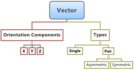
You can create the following types of vectors in MotionView:
| • | Single Vector |
| • | Pair Vector (Asymmetric or Symmetric) |
When used to orient entities in MotionView, the corresponding axis of the markers of the entity (the primary axis that defines the entity direction) gets oriented in the same direction as that of the Vector. For example, when a vector is used to orient the direction of the revolute joint, the Z axis of the joint I and J Markers are oriented along the direction of the Vector.
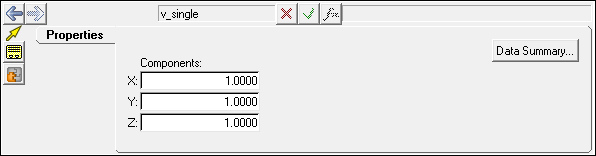
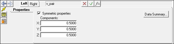
A Vector is primarily defined by its Cartesian Coordinates in the Global Frame. The only property that is applicable to the Vector entities are the components in the respective directions. The vector direction is determined along the direction of the coordinate values provided from the Global Origin. When creating Pair Vector entities, you have the option of making the Vector properties symmetric about the ZX plane of the model.
This entity does not have a graphical representation in the MotionView graphics area.
To learn how to add an "Entity" to a model, please see the Entity Manual topic.
OR
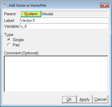
The Add Vector or VectorPair dialog is displayed.
Note - The selection of System collector for the entity can also be done after the entity has been added.
OR
Vector Panel - Properties Tab - Single Entity
Vector Panel - Properties Tab - Pair Entity
|
The Vector entity can be defined through the MDL format using the *Vector statement, and its property is set using the *SetVector statement. This entity by itself does not have a MotionSolve XML equivalent to it.
The Vector entity can be of the following types:
All of the types of entities mentioned above can be added to the model using the MDL Statements shown below:
To understand the complete syntax of the MDL statements mentioned above, please refer to the following MotionView MDL Reference Guide topics: *Vector(), *VectorPair(), *SetVector(). |
The Vector entity by itself does not have a MotionSolve XML equivalent to it. |
In MotionView, Tcl can be used to add any MDL entities to the model. There are two Tcl commands that can be used to add an entity:
Syntax: mdlmodel_handle InterpretEntity new_handle keyword varname label In case of the Vector the statement will look as shown below: mdlmodel_handle InterpretEntity Vector_handle Vector v_b "\"Torsion Axis Vector\""; |
Syntax: mdlmodel_handle InterpretSet keyword tokens; In case of the Vector the statement will look as shown below: mdlmodel_handle InterpretSet SetVector v_b 3.0 6.0 9.0; |
The InterpretEntity command is used to add entities to the model and the InterpretSet command is used to set the entity properties. To understand the complete usage and syntax of these commands, please refer to the following HyperWorks Desktop Reference Guide/Programming with Tcl/Tk Commands topics: InterpretEntity and InterpretSet.
Note - When using the InterpretEntity and InterpretSet commands, it is important to also use the Evaluate command in order for the changes to take effect immediately.
To learn how to create a complete model using Tcl commands, please refer to tutorial MV-1040: Model Building Using Tcl.
The following example shows the various Vector types that are used in MotionView:
*BeginMDL( the_model, "Model", "12.0.0.71" )
*StandardInclude(FILE) *SetCurrentSolverMode(MotionSolve) *Point( p_a, "Point A" ) *Body( b_a, "Body A", p_a, , , , ) *Set( p_a.x, 10 ) *Set( b_a.usecm, true ) *SetOrientation( b_a.cm, TWOAXES, ZX, DXDYDZ, , , , DXDYDZ ) *Set( THIS.state, )
#Example for Single Vector: *Vector( v_vec_single, "Vector_Single" )
#Example for a Pair Vector *VectorPair( v_vec_pair, "Vector _Pair" )
#Example for *SetVector statement. *SetVector( v_vec_single, 1.0, 1.0, 1.0 ) *SetVector( v_vec_pair, LEFT, -1.0, 2.0, 3.0 ) *EndMDL() |
See Also:
*Vector() (MDL Model Statement)
*VectorPair() (MDL Model Statement)
*SetVector() - single vector (MDL Model Statement)
*SetVector() - asymmetric pair (MDL Model Statement)
*SetVector() - symmetric pair (MDL Model Statement)
Reference_Marker (XML Command)
InterpretEntity (Tcl Command)
InterpretSet (Tcl Command)