|
»Click here to display Table of Contents«
|

Coupler |

|

|

|

|
|
Coupler |
|
|

|

|
|
»Click here to display Table of Contents«
|
Coupler |
|
|
|
|
|
Coupler |
|
|
|
|
This section describes the Coupler Joint entity of MotionView and shows the various usage, creation, and editing methods.
A Coupler entity defines an algebraic relationship between the degrees of freedom of two or three joints. This constraint element may be used to model idealized spur gears, rack and pinion gears, and differentials as simple constraints that relate the displacements in a set of joints. Couplers can be used to specify relationships between Translational, Rotational, and Cylindrical Joints only.
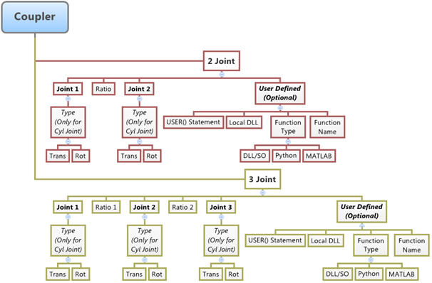
The topological information required to define an Coupler Joint is shown in the figure below:
The data members of the Coupler can be classified into the following members:
A Coupler relationship can be defined either between a set of two joints or between a set of three joints. The topological information required to define a Coupler is show in the figure above. A two joint Coupler needs the following:
A three joint Coupler needs the following:
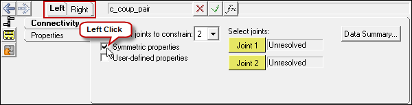
The joint can be modeled as a Single entity or as a Pair entity. |
Properties of a two Joint Coupler are:
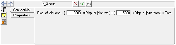
Properties of a three Joint Coupler are:
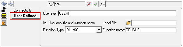
The USER function name for a Coupler entity can be COUSUB, COUXX, or COUXX2. The properties of a Coupler can be made symmetric with the Left or the Right Coupler acting as the Master property Coupler. |
To learn how to add a Coupler to a model, please see the Constraint Entities topic.
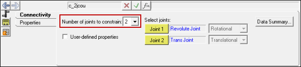
Coupler Panel – Connectivity Tab – Two Joints
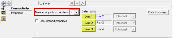
Coupler Panel – Connectivity Tab – Three Joints
The two joint Coupler definition needs two joints whose displacements are controlled by the Coupler ratio.
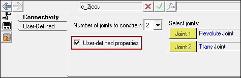
Note - The Properties tab will automatically change into the User-Defined tab.
The three joint Coupler definition needs three joints whose displacements are controlled by the Coupler ratio.
Note - The Properties tab will automatically change into the User-Defined tab.
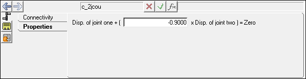
Coupler Panel - Properties Tab – Two Joints
Coupler Panel - Properties Tab – Three Joints
Coupler Panel - User-Defined Tab
Note - Steps 15 to 20 (above) apply to both Two Joint and Three Joint Coupler types.
Coupler Panel (Pair) – Connectivity Tab
Note - The same steps as shown above can also be used to define Pair Coupler entities. |
The Project Browser will filter the entities and display only the Couplers in the model.
The corresponding panel is automatically displayed.
|
The model containing the Coupler can be saved in MDL format from MotionView and exported in the MotionSolve XML format.
The Coupler entity can be of the following types:
All of the types of entities mentioned above can be added to the model using the MDL Statements shown below:
Please refer to the *Coupler, *CouplerPair, *SetCoupler, and *SetCouplerPair topics for a detailed description of each MDL statement. Note: To learn how to create a complete model using MDL statements, please refer to tutorial MV-1060: Introduction to MDL. |
The Coupler when exported to the MotionSolve XML format is defined as a Constraint_Coupler statement. Syntax: <Constraint_Coupler id = "integer" label = "Coupler Entity Label" joint1_id = "integer" freedom_1 = { "T" | "R" } joint2_id = "integer" freedom_2 = { "T" | "R" } [ joint3_id = "integer" freedom_3 = { "T" | "R" } ] { coefficients = "double, double [, double]" | usrsub_dll_name = "valid_path_name" usrsub_param_string = "USER( [[par_1][, ...][, par_n]] )" usrsub_fnc_name = "custom_fnc_name" > | script_name = valid_path_name interpreter = "PYTHON" | "MATLAB" usrsub_param_string = "USER( [[par_1 [, ...][,par_n]] )" usrsub_fnc_name = "custom_fnc_name" > } </Constraint_Coupler> In case of a three joint Coupler with linear properties the model statement will be as shown below: <Constraint_Coupler id = "301002" label = "Three Joint Coupler" joint1_id = "301003" freedom_1 = "R" joint2_id = "301004" freedom_2 = "R" joint3_id = "301005" freedom_3 = "R" coefficients = "1. 1. 1.5" /> In case of a three joint Coupler with User-defined properties, the model statement will be as shown below: <Constraint_Coupler id = "101004" label = "Coupler Pair User-left" joint1_id = "101006" freedom_1 = "R" joint2_id = "101007" freedom_2 = "R" joint3_id = "101008" freedom_3 = "R" usrsub_param_string = "USER(301001,301003,25)" usrsub_dll_name = "C:/Models/COUSUB.dll" usrsub_der1_name = "COUXX" usrsub_der2_name = "COUXX2" /> To understand the complete syntax of the Constraint_Coupler XML model statement, please refer to the MotionSolve Reference Guide Page for Constraint_Coupler. |
In MotionView, Tcl can be used to add any MDL entities to the model. There are two TCL commands that can be used to add an entity:
Syntax: mdlmodel_handle InterpretEntity new_handle keyword varname label In case of the Coupler the statement will look as shown below: mdlmodel_handle InterpretEntity joint Coupler c_jcoup "\"Two Joint Coupler\"" 2JOINT j_transjt j_RevJt "TRANS" "ROT" ; |
Syntax: mdlmodel_handle InterpretSet keyword tokens; In case of the Coupler the statement will look as shown below: mdlmodel_handle InterpretSet SetCoupler c_jcoup -0.9; |
The InterpretEntity command is used to add entities to the model and the InterpretSet command is used to set the entity properties. So in the case of the Coupler, the properties that can be set are the Joint Initial Conditions. Extended definitions for InterpretEntity and InterpretSet can be found in the HyperWorks Desktop Reference Guide.
Note - When using the InterpretEntity and InterpretSet commands, it is important to also use the Evaluate command in order for the changes to take effect immediately.
To learn how to create a complete model using Tcl commands, please refer to tutorial MV-1040: Model Building Using Tcl.
See Also:
*Coupler (MDL Model Statement)
*CouplerPair (MDL Model Statement)
Constraint_Coupler (XML Command)
InterpretEntity (Tcl Command)
InterpretSet (Tcl Command)