This section describes the Surface to Surface (SFSF) Joint entity of MotionView and shows the various usage, creation, and editing methods.
Theory/Background
The Surface to Surface Joint defines a higher pair constraint. The constraint consists of a surface on one body rolling and sliding on the surface of a second body. Each of the surfaces are required to have a unique contact point. The Surface to Surface Joint constrains the two surfaces as follows:
| • | The surfaces have exactly one contact point. |
| • | The normal at the contact point for each surface are anti-parallel. |
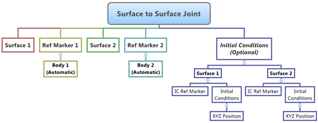
The topological information required to define an SFSF Joint is shown in the figure below:
Entity Data Members
The data members of the SFSF Joint can be classified into the following members:
Connectivity
An SFSF Joint needs the following:
| • | Two Bodies – Body 1 and Body 2. |
| • | Two Surfaces – Surface 1 and Surface 2 (each belonging to their respective bodies). |
| • | Two Reference Markers – Ref Marker 1 and Ref Marker 2 (each belonging to their respective bodies, and which also represent the coordinate systems that the surfaces are defined in). |
This advanced joint can only be modeled as a Single entity (it cannot be modeled as a Pair entity).
Properties
The SFSF Joint can have an optional Position Initial Conditions as the property.
| • | Both the surfaces of the SFSF Joint needs initial contact points defined. In absence of user input for the same, MotionView will measure the distance between all the points on the surfaces and pick two points, one of each surface, that are closed to each other. You can optionally specify the two contact points using the Use XYZ option. |
| • | Additionally, a unique Reference Marker can be specified for the Position initial conditions of each surface. By default this marker is the surface Reference Marker that belongs to Body 1 and Body 2 respectively. This marker is specified using the Use Initial Condition Marker check box. |
If the values for the Initial Contact Point are known for the SFSF joint, then it is recommended that they are specified while defining the joint.
Creating and Editing Joints
To learn how to add a Surface to Surface Joint to a model, please see the Joints topic.
Important Note - In order to completely specify a Surface to Surface Joint, the following entities must be created first:
| 1. | Two reference surface entities (created using the Surfaces panel  ). ). |
| 2. | Two Markers that belong to Body 1 and Body 2 of the Joint and are located appropriately so that the Surface entity can be meaningfully described as belonging to the Coordinate System of the Reference Marker. |
| 1. | Once an SFSF Joint has been added to the model using any of the "entity" creation methods, the panel for the joint will automatically be displayed in the panel area. See the panel examples below: |
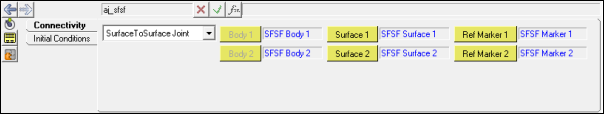
Joints Panel (SFSF Joint) – Connectivity Tab
| 2. | In order to complete the joint definition, four entities have to be specified. From Connectivity tab, double-click the Surface 1 collector and select the surface that belongs to Body 1 from the model tree. |
| 3. | Next, double-click the Surface 2 collector and select the surface that belongs to Body 2 from the model tree. . |
| 4. | Click on the Ref Marker 1 collector and select the reference marker that belongs to Body 1. |
| 5. | In the same manner, click on the Ref Marker 2 collector and select the reference marker that belongs to Body 2. |
The Body 1 and Body 2 fields are automatically populate with the appropriate body labels (as demonstrated in the figure above).
| 6. | Click on the Initial Conditions tab. |
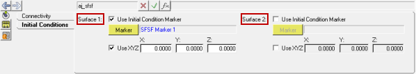
Joints Panel (SFSF Joint) – Initial Conditions Tab
For each of the surfaces of the SFSF joint, there are two optional properties that can be set - the Initial Condition Marker and the Initial Contact Point Coordinates.
| 7. | The default Initial Condition Marker for the joint is the Ref Marker that is specified on the Connectivity tab. To change it, activate the Use Initial Condition Marker check box and select the desired marker. |
| 8. | To specify an initial contact point for each surface, activate the Use XYZ check box and type in the initial point coordinates. |
|
| 1. | Left click the Advanced Joints panel icon  on the Constraint toolbar. on the Constraint toolbar. |
The Project Browser will filter the entities and display only the Advanced Joints in the model.
| 2. | Select the desired joint in the Project Browser. |
The corresponding panel is automatically displayed.
| 3. | From the Connectivity tab, use the Joint type drop-down menu to change the joint type, or use the collectors to change the bodies and topological/property attributes of the joint. |
|
Surface to Surface Joint in MDL and XML Formats
The model containing the SFSF Joint can be saved in MDL format from MotionView and exported in the MotionSolve XML format.
Syntax:
*SurfaceToSurfaceJoint(sfsf_name, "sfsf_label", body_1,
body_2,
surface_1,
surface_2,
ref_marker_1,
ref_marker_2,
[icm_1],
[icm_2])
Example:
*SurfaceToSurfaceJoint(aj_sfsf, "Surface to Surface Joint", b_sfb1, b_sfb2, sur_sf1, sur_sf2, m_sfm1, m_sfm2, aj_sfsf.rm1, aj_sfsf.rm2)
To understand the complete syntax of the MDL statement please refer to the *SurfaceToSurfaceJoint topic.
|
The *SetJointIC statement can be used for specifying initial conditions for the joint:
Syntax:
*SetJointIC(joint_name, i_ic_x_disp,
i_ic_y_disp,
i_ic_z_disp,
,
j_ic_x_disp,
j_ic_y_disp,
j_ic_z_disp)
Example:
*SetJointIC(aj_sfsf, 266.0, 658.52, 10, , 45, 22, 0.5)
To understand the complete syntax of the MDL statements please refer to the *SetJointIC topic.
|
To learn how to create a complete model using MDL Statements please refer to tutorial MV-1060: Introduction to MDL.
|
The SFSF Joint when exported to the MotionSolve XML format is defined as a Constraint_SFSF statement.
Syntax:
<Constraint_SFSF
id = "integer"
label = "Advanced Joint Label"
i_marker_id = "integer"
i_surface_id = "integer"
i_disp_x0 = "real"
i_disp_y0 = "real"
i_disp_z0 = "real"
j_marker_id = "integer"
j_surface_id = "integer"
j_disp_x0 = "real"
j_disp_y0 = "real"
j_disp_z0 = "real"
</Constraint_SFSF>
In case of the SFSF Joint the model statement will be as shown below:
<Constraint_SFSF
id = "301001"
label = "Surface to Surface Joint"
i_marker_id = "30102022"
j_marker_id = "30103032"
i_disp_x0 = "266."
i_disp_y0 = "658.52"
i_disp_z0 = "10."
j_disp_x0 = "45."
j_disp_y0 = "22."
j_disp_z0 = "0.5"
i_surface_id = "301001"
j_surface_id = "301002"
/>
In the above XML Model statement the i_marker_id and j_marker_id represent the I and J markers of the Joint which belong to Body 1 and Body 2 respectively. To understand the complete syntax of the Constraint_SFSF XML model statement, please refer to the MotionSolve Reference Guide Page for Constraint_SFSF.
|
Creating and Editing Surface to Surface Joints using Tcl
In MotionView, Tcl can be used to add any MDL entities to the model. There are two Tcl commands that can be used to add an entity:
Syntax:
mdlmodel_handle InterpretEntity new_handle keyword varname label
In case of the SFSF Joint the statement will look as shown below:
mdlmodel_handle InterpretEntity advjoint SurfaceToSurfaceJoint aj_sfsf "\"Surface to Surface Joint\"" b_sfb1 b_sfb2 sur_sf1 sur_sf2 m_sfm1 m_sfm2 aj_sfsf.rm1 aj_sfsf.rm2;
|
The initial conditions for the Surface to Surface Joint can be specified using the InterpretSet Tcl command.
Syntax:
mdlmodel_handle InterpretSet keyword tokens
In case of the SFSF Joint the statement will look as shown in the example below:
mdlmodel_handle InterpretSet SetJointIC aj_sfsf 266.0 658.52 10 "" 45 22 0.5;
|
The InterpretEntity command is used to add entities to the model and the InterpretSet command is used to set the entity properties. So in the case of the Surface to Surface Joint, the properties that can be set are the Joint Initial Conditions. Extended definitions for InterpretEntity and InterpretSet can be found in the HyperWorks Desktop Reference Guide.
Note - When using the InterpretEntity and InterpretSet commands, it is important to also use the Evaluate command in order for the changes to take effect immediately.
To learn how to create a complete model using Tcl commands, please refer to tutorial MV-1040: Model Building Using Tcl.
See Also:
Advanced Joints Panel
Adding and Removing Entities
*SurfaceToSurfaceJoint (MDL Model Statement)
*Surface (MDL Model Statement)
*SetJointIC (MDL Model Statement)
Constraint_SFSF (XML Command)
InterpretEntity (Tcl Command)
InterpretSet (Tcl Command)


