This section describes the Point to Surface (PTSF) Joint entity of MotionView and shows the various usage, creation, and editing methods.
Theory/Background
A Point to Surface Joint is a higher pair constraint, which constrains a fixed point on a body to slide along a Surface. The Point to Surface joint provides five degrees of freedom: three rotational at the instantaneous point of contact and two translational DOF.
Common Applications of PTSF Joints are:
| • | Manufacturing Simulations |
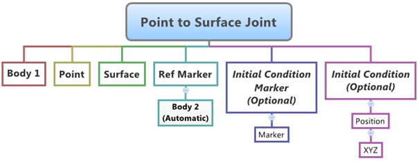
The topological information required to define an PTSF Joint is shown in the figure below:
Entity Data Members
The data members of the PTSF Joint can be classified into the following members:
Connectivity
An PTSF Joint needs the following:
| • | Point on Body 1 that is constrained to the Surface - Point. |
| • | The Surface that belongs to Body 2. |
| • | Reference Marker with respect to which Surface is created above - Ref Marker. |
Properties
If required, the following Initial conditions can be specified for the joint:
| • | An Initial Condition Marker can be specified for applying the initial conditions. |
| • | An XYZ Initial Position Condition can be specified for the Point. |
If initial conditions are known, it is better to specify them while defining the joint as this will help reduce chances of error in results. If the initial conditions are not specified, MotionView will calculate the point on the surface that is nearest to the Point specified for the Joint.
Creating and Editing Joints
To learn how to add a Point to Surface Joint to a model, please see the Joints topic.
Important Note - In order to completely specify a Point to Surface Joint, the following entities must be created first:
| 1. | A 3D Surface entity (created using the Surfaces panel  ). ). |
| 2. | A Marker that belongs to Body 2 of the joint and is located appropriately so that the Surface entity can be meaningfully described as belonging to the Coordinate System of the Reference Marker. |
| 1. | Once an PTSF Joint has been added to the model using any of the "entity" creation methods, the panel for the joint will automatically be displayed in the panel area. See the panel examples below: |
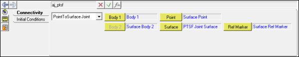
Joints Panel (PTSF Joint) – Connectivity Tab
| 2. | The joint definition needs two bodies which are connected by the joint. From Connectivity tab, select Body 1 from the graphics area, or double click the Body 1 collector to open to the model tree (from which the desired body can be selected). |
| 3. | Use the Point collector/model tree to specify the point of the PTSF joint (or activate the collector and pick the point from the graphics area). |
| 4. | Use the Surface collector/model tree to select the predefined surface for the joint (or activate the collector and pick the surface from the graphics area). |
| 5. | Select the Surface Reference Marker (Ref Marker) that belongs to Body 2. |
| 6. | Click on the Initial Conditions tab. |
| 7. | The default Initial Condition Marker for the joint is the Ref Marker that is specified on the Connectivity tab. To change it, activate the Use Initial Condition Marker check box and select the desired marker. |
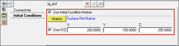
Joints Panel (PTSF Joint) – Initial Conditions Tab
| 8. | To specify an initial position for the Point to supersede those specified by the Point on the Connectivity tab, activate the Use XYZ check box and type in the initial position values. |
|
| 1. | Left click the Advanced Joints panel icon  on the Constraint toolbar. on the Constraint toolbar. |
The Project Browser will filter the entities and display only the Advanced Joints in the model.
| 2. | Select the desired joint in the Project Browser. |
The corresponding panel is automatically displayed.
| 3. | From the Connectivity tab, use the Joint type drop-down menu to change the joint type, or use the collectors to change the bodies and origins/alignment points of the joint. |
|
Point to Surface Joint in MDL and XML Formats
The model containing the PTSF Joint can be saved in MDL format from MotionView and exported in the MotionSolve XML format.
Syntax:
*PointToSurfaceJoint(ptsf_name, "ptsf_label", body_1,
body_2,
point,
surface,
ref_marker,
[icm],
[ALLOW_COMPLIANCE])
Example:
*PointToSurfaceJoint(aj_ptsf, "Point to Surface Joint", b_b1, b_b2surf, p_sfpt, sur_ptsf, m_b2refmark, MODEL.m_b2refmark)
To understand the complete syntax of the MDL statement please refer to the *PointToSurfaceJoint topic.
|
The *SetJointICFlag and *SetJointIC statements can be used for specifying initial conditions for the joint:
Syntax:
*SetJointICFlag(joint_name, true|false)
*SetJointIC(joint_name, ic_x_disp, ic_y_disp, ic_z_disp)
Example:
*SetJointICFlag(aj_ptsf, true)
*SetJointIC(aj_ptsf, 200, 150, 255)
To understand the complete syntax of the MDL statements please refer to the *SetJointICFlag and *SetJointIC topics.
|
To learn how to create a complete model using MDL Statements please refer to tutorial MV-1060: Introduction to MDL.
|
The PTSF Joint when exported to the MotionSolve XML format is defined as a Constraint_PTSF statement.
Syntax:
<Constraint_PTSF
id = "integer"
label = "Advanced Joint name"
i_marker_id = "integer"
j_marker_id = "integer"
[
disp_xo = "real"
disp_yo = "real"
disp_zo = "real"
]
surface_id = "integer" >
/>
In case of the PTSF Joint the model statement will be as shown below:
<Constraint_PTSF
id = "301001"
label = "Point to Surface Joint"
i_marker_id = "30102030"
j_marker_id = "30103040"
disp_x0 = "200."
disp_y0 = "150."
disp_z0 = "255."
surface_id = "301001"
/>
In the above XML Model statement the i_marker_id and j_marker_id represent the I and J markers of the Joint which belong to Body 1 and Body 2 respectively. To understand the complete syntax of the Constraint_PTSF XML model statement, please refer to the MotionSolve Reference Guide Page for Constraint_PTSF.
|
Creating and Editing Point to Surface Joints using Tcl
In MotionView, Tcl can be used to add any MDL entities to the model. There are two Tcl commands that can be used to add an entity:
Syntax:
mdlmodel_handle InterpretEntity new_handle keyword varname label
In case of the PTSF Joint the statement will look as shown below:
mdlmodel_handle InterpretEntity aj PointToSurfaceJoint aj_0 "\"Advanced Joint 0\"" b_0 b_0 p_0 sur_0 m_0;
|
The initial conditions for the Point to Surface Joint can be specified using the InterpretSet Tcl command.
Syntax:
mdlmodel_handle InterpretSet keyword tokens
In case of the PTSF Joint the statement will look as shown in the example below:
mdlmodel_handle InterpretSet SetJointICFlag aj_0 "true";
mdlmodel_handle InterpretSet SetJointIC aj_0 250 150 255;
|
The InterpretEntity command is used to add entities to the model and the InterpretSet command is used to set the entity properties. So in the case of the Point to Surface Joint, the properties that can be set are the joints Initial Conditions. Extended definitions for InterpretEntity and InterpretSet can be found in the HyperWorks Desktop Reference Guide.
Note - When using the InterpretEntity and InterpretSet commands, it is important to also use the Evaluate command in order for the changes to take effect immediately.
To learn how to create a complete model using Tcl commands, please refer to tutorial MV-1040: Model Building Using Tcl.
See Also:
Advanced Joints Panel
Adding and Removing Entities
*PointToSurfaceJoint (MDL Model Statement)
*SetJointIC (MDL Model Statement)
Constraint_PTSF (XML Command)
InterpretEntity (Tcl Command)
InterpretSet (Tcl Command)


