|
»Click here to display Table of Contents«
|

Joints |

|

|

|

|
|
Joints |
|
|

|

|
|
»Click here to display Table of Contents«
|
Joints |
|
|
|
|
|
Joints |
|
|
|
|
This section provides an overview of the Joint entity in MotionView.
Joints create lower pair constraints. A lower pair is an idealized form of constraint where the constraint can be represented using two reference frames, or coordinate systems, belonging to two different bodies. The origin, axis, or plane of one reference frame is said to be constrained with respect to the origin, axis, or plane of another reference frame. For example, a translation joint constraints a point on one body with regard to coordinate planes on another body. In this case, the point can only translate along a vector of the coordinate system. The body is said to have only a translation degree of freedom free, while the remaining two translational and all rotational degrees of freedom are restrained.
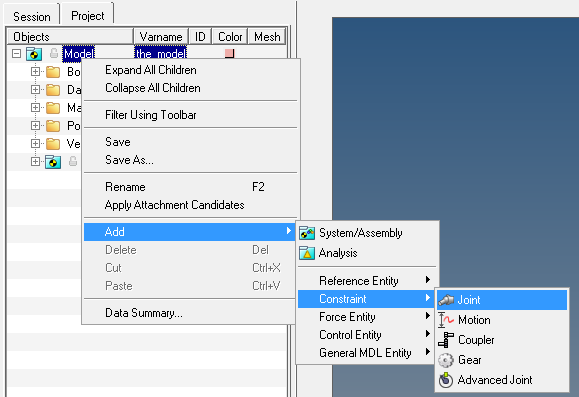
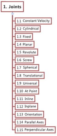
The figure below shows the various types of Joints that are supported in MotionView:
To learn how to add an "Entity" to a model, please see the Entity Manual topic.
OR
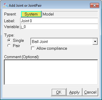
The Add Joint or JointPair dialog is displayed.
The label can be a descriptive name.
The recommended naming convention for creating joints is that all joint variable names should begin with j_. Further, the variable name can be descriptive however it should not contain any special characters (other than ‘underscore’).
A Joint entity, like most of the entities that are created in MotionView, can be a Single Entity or a Pair Entity. Pair entities help in creating models which have symmetric properties.
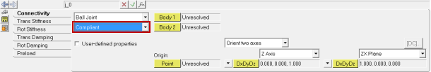
A Joint when made compliant, will be treated as a Bushing entity and all the properties of the Joint will now be the same as the properties of a Bushing.
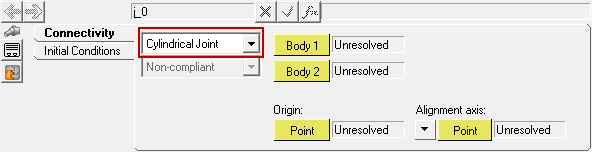
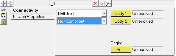
The Connectivity tab displays the type of joint that was created. The joint type can be modified using the drop down menu. Other members/tabs in the panel will vary depending on the type of joint.
The drop-down menu below the Joint type drop-down menu is activated and the joint can be made compliant if need be.
Additional tabs are added to the panel which allow the specification of Translation Stiffness, Rotational Stiffness, Translational Damping, Rotational Damping, and Preload. These are tabs are similar to the tabs located on the Bushings panel, and the behavior of a Compliant joint is exactly the same to the behavior of a bushing entity. |
The table below shows the list of joints that can be created in MotionView along with the Degrees of Freedom (DOF) that each joint removes:
Joint Type |
Translational Constraints |
Rotational Constraints |
Total Constraints |
|---|---|---|---|
3 |
0 |
3 |
|
3 |
1 |
4 |
|
2 |
2 |
4 |
|
3 |
3 |
6 |
|
2 |
0 |
2 |
|
1 |
0 |
1 |
|
0 |
3 |
3 |
|
0 |
2 |
2 |
|
0 |
1 |
1 |
|
1 |
2 |
3 |
|
3 |
2 |
5 |
|
0.5 |
0.5 |
1 |
|
3 |
0 |
3 |
|
2 |
3 |
5 |
|
3 |
1 |
4 |
| Note | Click on the individual links (above) to learn more about each specific joint type. |
See Also: