|
»Click here to display Table of Contents«
|

Cylindrical Joint |

|

|

|

|
|
Cylindrical Joint |
|
|

|

|
|
»Click here to display Table of Contents«
|
Cylindrical Joint |
|
|
|
|
|
Cylindrical Joint |
|
|
|
|
This section describes the Cylindrical joint entity of MotionView and shows the various usage, creation, and editing methods.
A Cylindrical joint is a two degree-of-freedom kinematic pair used in mechanisms. Cylindrical joints provide one translation and one rotation function.
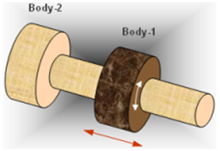
Cylindrical joint construction
Cylindrical Joints are commonly used in many places, such as:
| • | Shock absorber tube and rod |
| • | Hydraulic cylinder/rod pair |
The Cylindrical joint is represented using Markers when exported to an MBD Solver. The representation can be visualized as shown in the figure below:
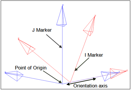
Cylindrical joint marker representation
The bodies that are constrained by the Cylindrical joint are represented using two markers: Marker I and Marker J. Marker I belongs to Body 1 and Marker J belongs to Body 2. The constraints and displacement are applied on the Marker I with respect to the Marker J. Both of the markers will have a common point of origin, the same as the joint’s Origin Point. The orientation axis of the Cylindrical joint is represented by the Z axis of both I and J markers. Thus, the Markers I and J share a common point of origin and the direction of orientation of their Z axes. Marker I is free to translate along and rotate about the Z axis of the Marker J.
The topological information required to define an Cylindrical Joint is shown in the figure below:
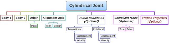
The data members of the Cylindrical joint can be classified into the following members:
An Cylindrical joint needs the following:
| • | Body 1 and Body 2 - Specify two Bodies between which the joint is to be created. |
| • | Origin - Specify Point, which defines the location of the joint. |
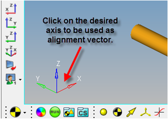
| • | Alignment Axis - Orientation of the joint specified using a Point or Vector. |
| • | Compliant Mode (Optional) - If required, the joint’s Compliant Mode can be set to True (in order to make it compliant). |
| • | Friction Properties (Optional) - Friction properties can be assigned to a Cylindrical joint. |
The joint can be modeled as a Single entity or as a Pair entity.
| Note | Displacement Initial Conditions for Joints is not supported by MotionSolve as of version 12.0. Only Velocity Initial Conditions are supported by MotionSolve. Displacement Initial Conditions can be specified when building models using the ADAMS Solver. |
Optional Initial Conditions can also be specified for the joint:
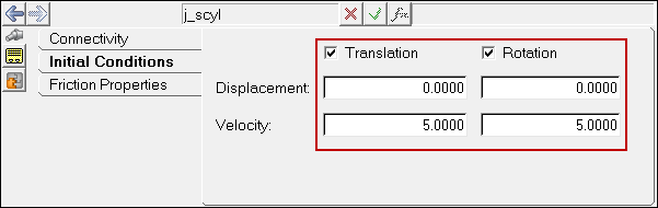
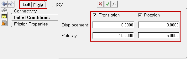
| • | Since the joint has one translational DOF and one rotational DOF, the joint can have one set of Translational Initial Conditions (Displacement and Velocity) and one set of Rotational Initial Conditions. |
| Note | Displacement Initial Conditions are not supported by MotionSolve version 12.0. This option can only be when building models using the ADAMS Solver. |
| • | The editable properties of a Cylindrical Joint are the Translational and Rotational Initial Conditions of the joint. |
| • | When modeled as a Pair entity, the joint can have symmetric properties. |
Optional Friction properties can also be specified for the joint:
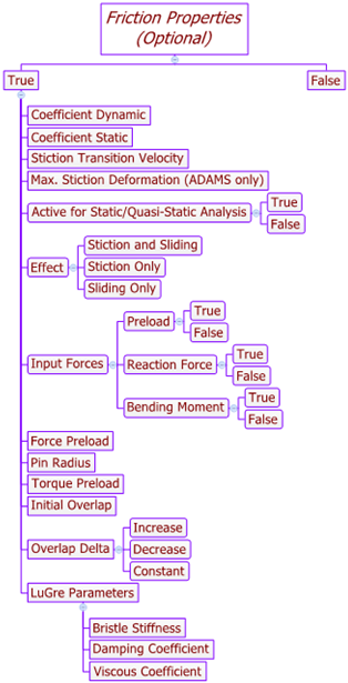
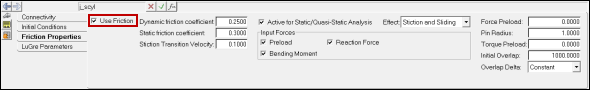
Activating the Use Friction option on the Friction Properties tab will display the following options in the panel:
Coefficient Dynamic |
|
||||||
Coefficient Static |
|
||||||
Stiction Transition Velocity |
|
||||||
Max. Stiction Deformation (Adams only) |
|
||||||
Active for Static/Quasi-Static Analysis |
True/False |
||||||
Effect |
|
||||||
Input Forces |
|
||||||
Force Preload |
|
||||||
Pin Radius |
|
||||||
Torque Preload |
|
||||||
Initial Overlap |
|
||||||
Overlap Delta |
|
||||||
LuGre Parameters |
|
To learn how to add a Cylindrical joint to a model, please see the Joints topic.
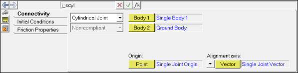
Joints Panel (Cylindrical Joint) – Connectivity Tab - Single Entity
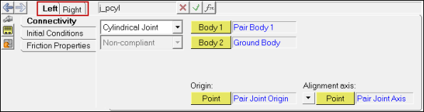
Joints Panel (Cylindrical Joint) – Connectivity Tab - Pair Entity
Joints Panel (Cylindrical Joint) – Initial Conditions Tab - Single Entity
Joints Panel (Cylindrical Joint) – Initial Conditions Tab - Pair Entity
Joints panel - Friction Properties tab Checking the Use Friction option displays a set of input fields which you need to specify as needed by the friction model of the solver. In addition, the LuGre Parameters tab also appears if the SolverMode is set to MotionSolve.
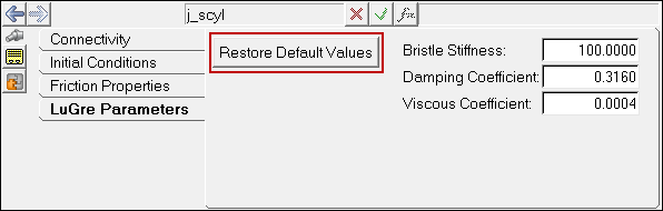
Joints panel - LuGre Parameters tab For additional details on the various fields in the Friction Properties and LuGre Parameters tab, please refer to the Joints Panel – Friction Properties Tab and Joints Panel - LuGre Parameters Tab topics. Based on the joint selection, the relevant fields will be displayed in the Friction Properties tab. These fields are populated by default values as shown above. You can click the Restore Default Values button in the LuGre Parameters tab in order to populate default LuGre parameters. Note - The same steps as shown above can also be used to define Pair Cylindrical Joint entities. When defining a Pair Cylindrical Joint use pair entities for Body 1, Body 2, Origin, etc. |
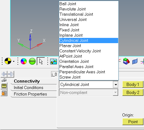
The Project Browser will filter the entities and display only the Joints in the model.
The corresponding panel is automatically displayed.
Joints panel - Connectivity tab - joint type drop-down menu |
The model containing the Cylindrical Joint can be saved in MDL format from MotionView and exported in the MotionSolve XML format.
The Cylindrical Joint can be of the following types:
These four types of entities can be added to the model using MDL Statements shown below:
To learn how to create a complete model using MDL Statements please refer to tutorial MV-1060: Introduction to MDL. |
The Cylindrical Joint when exported to the MotionSolve XML format is defined as a Constraint_Joint statement. Syntax: <Constraint_Joint id = "integer" label = "Name of Joint" type = "JOINT TYPE" i_marker_id = "integer" j_marker_id = "integer" /> Initial Velocity Conditions of the Cylindrical Joint are defined using JointInitialVel_Cyl the statement: <JointInitialVel_Cyl joint_id = "integer" trans_iv = "real" rot_iv = "real" /> In the case of the Cylindrical Joint the model statement will be as shown below: <Constraint_Joint id = "301001" label = "Cyl Joint" type = "CYLINDRICAL" i_marker_id = "30103050" j_marker_id = "30101050" /> In the above XML Model statement the i_marker_id and j_marker_id represent the I and J markers of the Joint which belong to Body 1 and Body 2 respectively. To understand the complete syntax of the Constraint_Joint XML model statement, please refer to the MotionSolve Reference Guide Page for Constraint_Joint. Initial Conditions Example: <JointInitialVel_Cyl joint_id = "301001" trans_iv = "5." rot_iv = "15." /> |
In MotionView, Tcl can be used to add any MDL entities to the model. There are two Tcl commands that can be used to add an entity:
Syntax: mdlmodel_handle InterpretEntity new_handle keyword varname label Example: mdlmodel_handle InterpretEntity joint_cyl_handle CylJoint j_cyl "\"Cyl Joint\"" b_1 B_Ground p_ori "POINT" p_axis "ALLOW_COMPLIANCE"; |
Syntax: mdlmodel_handle InterpretSet keyword tokens Example: mdlmodel_handle InterpretSet SetJointICFlag j_cyl "TRANS" "true" mdlmodel_handle InterpretSet SetJointICFlag j_cyl "ROT" "true" mdlmodel_handle InterpretSet SetJointIC j_cyl "TRANS" "0.0" "15.0" mdlmodel_handle InterpretSet SetJointIC j_cyl "ROT" "0.0" "15.0"
mdlmodel_handle InterpretSet SetJointFriction j_cyl true mu_static mu_dynamic use_static transition_vel max_deformation effect preload_input reaction_force_input bending_moment_input torsional_moment_input f_preload reaction_arm initial_overlap overlap_delta rot_constraint t_preload pin_radius friction_arm bending_reaction_arm ball_radius
mdlmodel_handle InterpretSet SetJointFrictionLugre j_cyl bristle_stiffness damping_effects viscous_effects |
The InterpretEntity command is used to add entities to the model and the InterpretSet command is used to set the entity properties. So in the case of the Cylindrical Joint, the properties that can be set are the joint Initial Conditions and joint Friction. Extended definitions for InterpretEntity and InterpretSet can be found in the HyperWorks Desktop Reference Guide.
Note - When using the InterpretEntity and InterpretSet commands, it is important to also use the Evaluate command in order for the changes to take effect immediately.
To learn how to create a complete model using Tcl commands, please refer to tutorial MV-1040: Model Building Using Tcl.
Example Model
The example file below shows a Cylindrical joint connecting two bodies:
*BeginMDL( the_model, "Model" ) *StandardInclude(FILE) *Point( p_0, "Point 0" ) *PointPair( p_1, "Point 1" ) *Body( b_0, "Body 0", p_0, , , , ) *BodyPair( b_1, "Body 1", p_1, , , , ) //Example for a Cylindrical Joint - Single *CylJoint( j_cyljsingle, "Cylindrical Joint Single", b_0, B_Ground, p_0, POINT, p_1.r ) //Example for a Cylindrical Joint - Pair *CylJointPair( j_cyljpairsym, "Cylindrical Joint Pair Sym", b_1, B_Ground, p_1, VECTOR, V_Global_Y ) *CylJointPair( j_cyljpairAsym, "Cylindrical Joint pair Asym", b_1, B_Ground, p_1, VECTOR, V_Global_Y ) *SetPoint( p_1, LEFT, , -100 ) *Set( b_0.usecm, true ) *Set( b_1.usecm, true ) *SetBodyInertia( b_1, LEFT, 1, 10000, 10000, 10000 ) //Example for SetJointICFlag - Single *SetJointICFlag( j_cyljsingle, ROT, true ) //Example for SetJointIC - Single *SetJointIC( j_cyljsingle, ROT, , 5 ) //Setting joint friction using SetJointFriction - Single *SetJointFriction( j_cyljsingle, true, 0.35, 0.26, ACTIVE_STATIC, 0.15, , STICTION_AND_SLIDING, PRELOAD, REACTION_FORCE, , , 1000, 25, , , , 1000, , , , 10 ) //Setting joint friction LuGre parameters using SetJointFrictionLugre - Single *SetJointFrictionLugre( j_cyljsingle, 100, 0.316, 0.0004 ) //Example for SetJointICFlag – Symmetric Pair *SetJointICFlag( j_cyljpairsym, LEFT, ROT, true ) //Example for SetJointIC - Symmetric Pair *SetJointIC( j_cyljpairsym, LEFT, ROT, 0, 10 ) //Setting joint friction using SetJointFriction - Symmetric Pair *SetJointFriction( j_cyljpairsym, LEFT, true, 0.35, 0.26, ACTIVE_STATIC, 0.15, , STICTION_AND_SLIDING, NO_PRELOAD, REACTION_FORCE, BENDING_MOMENT, , 2000,25 , , , , 1000, 10, 15, 50 ) //Example for SetJointICFlag – Asymmetric Pair *SetJointICFlag( j_cyljpairAsym, , ROT, true, true ) //Example for SetJointIC - Asymmetric Pair *SetJointIC( j_cyljpairAsym, , ROT, , 5, , 10 ) //Setting joint friction using SetJointFriction - Asymmetric Pair *SetJointFriction( j_cyljpairAsym, , true, 0.35, 0.26, ACTIVE_STATIC, 0.15, , STICTION_ONLY, PRELOAD, REACTION_FORCE, , ,1000, 30, , , , 1000, , , , 10 , true, 0.35, 0.26, ACTIVE_STATIC, 0.15, , STICTION_ONLY, PRELOAD, REACTION_FORCE, , ,1000, 30, , , , 1000, , , , 10 ) //Setting joint friction LuGre parameters using SetJointFrictionLugre - Pair *SetJointFrictionLugre( j_cyljpairAsym, 100, 0.316, 0.0004 , 100, 0.316, 0.0004 ) *EndMDL() |
See Also:
*CylJoint (MDL Model Statement)
*CylJointPair (MDL Model Statement)
*SetJointIC (MDL Model Statement)
Constraint_Joint (XML Command)
InterpretEntity (Tcl Command)
InterpretSet (Tcl Command)