|
»Click here to display Table of Contents«
|

Joints Panel |

|

|

|

|
|
Joints Panel |
|
|

|

|
|
»Click here to display Table of Contents«
|
Joints Panel |
|
|
|
|
|
Joints Panel |
|
|
|
|
The Joints panel allows you to edit the connectivity, properties, and orientation rules of joints.
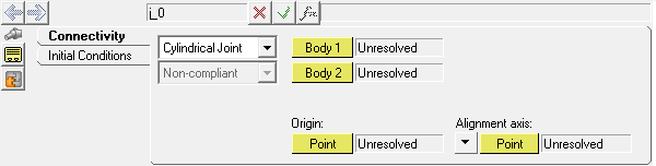
Joints panel
MotionView joints can be toggled between compliant and non-compliant.
Non-compliant joints act as pure constraints and allow relative motion only between the degrees of freedom of that particular joint type.
The Joints panel contains the following tabs for non-compliant joints:
Compliant joints are identical to bushings and allow relative motion in all six degrees freedom. The relative motion will be dependent on the stiffness and damping of the compliant joint. In order for a joint to be compliant, the Allow compliance option must be enabled at the time of joint creation.
For compliant joints, the following additional tabs are displayed:
Symmetric properties |
allows you to turn symmetry on or off. When symmetry is turned off, both sides can be edited separately. When you turn on symmetry, you are prompted to select a parent side. |
User-defined |
define non-linear stiffness and damping properties from a user-defined dll. After you select User-defined properties, select the User-Defined tab. You can then select a force from the drop-down menu and also enter the user-defined function. |
You can create the following types of joints:
Ball |
Planar |
Revolute |
Constant Velocity |
Translational |
Atpoint |
Universal |
Orientation |
Inline |
Parallel Axes |
Fixed |
Perpendicular Axes |
Inplane |
Screw |
Cylindrical |
|
| Note | The connectivity and orientation information of a joint and bushing are identical. A joint places a combination of rigid constraints between two bodies, and a bushing places compliant constraints between bodies. |
Joint Primitive Type |
Removes Number of Translational DOF |
Removes Number of Rotational DOF |
Removes Total Number DOF |
|---|---|---|---|
Atpoint |
3 |
0 |
3 |
Inline |
2 |
0 |
2 |
Inplane |
1 |
0 |
1 |
Orientation |
0 |
3 |
3 |
Parallel Axes |
0 |
2 |
2 |
Perpendicular |
0 |
1 |
1 |
Joint Type |
Removes Translational DOF |
Removes Rotational DOF |
Removes Total Number DOF |
|---|---|---|---|
Ball Joint |
3 |
0 |
3 |
Constant Velocity |
3 |
1 |
4 |
Cylindrical |
2 |
2 |
4 |
Fixed |
3 |
3 |
6 |
Planar |
1 |
2 |
3 |
Point to Curve |
2 |
0 |
2 |
Revolute |
3 |
2 |
5 |
Translational |
2 |
3 |
5 |
Universal |
3 |
1 |
4 |
OR
OR
The Add Joint or JointPair dialog is displayed.
|
The System/Assembly panel is automatically displayed.
|