|
»Click here to display Table of Contents«
|

Planar Joint |

|

|

|

|
|
Planar Joint |
|
|

|

|
|
»Click here to display Table of Contents«
|
Planar Joint |
|
|
|
|
|
Planar Joint |
|
|
|
|
This section describes the Planar joint entity of MotionView and shows the various usage, creation, and editing methods.
A Planar joint is a three degree-of-freedom constraint. It constrains a plane on one body (Body 1) to remain in a plane defined on the other body (Body 2) connected by the joint. The planes are defined by the X and Y axes of the markers defining the joint. Body 1 can rotate about Z axis and translate along the X and Y axes of the marker which is used to define the constraint.
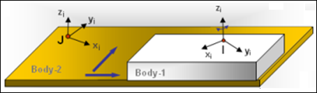
Planar joint construction
The Planar joint is represented using Markers when exported to an MBD Solver. The representation can be visualized as shown in the figure below:
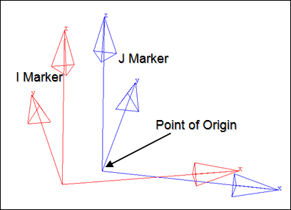
Planar joint marker representation
The bodies that are constrained by an Planar joint are represented using two markers: Marker I and Marker J. Marker I belongs to Body 1 and Marker J belongs to Body 2. The constraints are applied on Marker I with respect to Marker J. Both the markers will have a common point of origin, the same as the joint’s Origin point. The XY plane of Marker I will be constrained to remain on the XY plane of Marker J. However, Marker I can translate anywhere on the plane and rotate about its Z axis.
The topological information required to define an Planar joint is shown in the figure below:
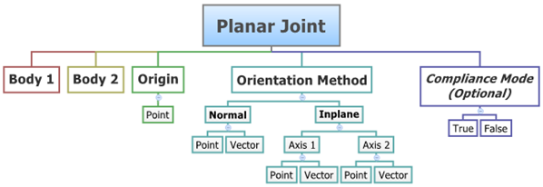
The data members of the Planar joint can be classified into the following members:
An Planar joint needs the following:
| • | Body 1 and Body 2 - Specify two Bodies between which the joint is to be created. |
| • | Origin - Specify Point, which defines the location of the joint. |
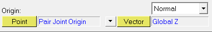
| • | Orientation Method - An Planar joint needs a plane to be specified for the constraint to be imposed. This can be done by specifying the normal to the plane or the plane itself. |
| • | Compliant Mode (Optional) - If the Allow Compliance option is selected while adding the joint to a model, the joint's compliance state can be toggled between Compliant and Non-Compliant. If the joint is made Compliant, it no longer remains a rigid connection and the joint will then be treated as a bushing. |
The joint can be modeled as a Single entity or as a Pair entity.
There are no editable properties for an Planar joint.
To learn how to add a Planar joint to a model, please see the Joints topic.
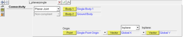
Joints Panel (Planar Joint) – Connectivity Tab - Single Entity
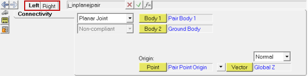
Joints Panel (Planar Joint) – Connectivity Tab - Pair Entity
OR
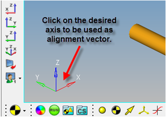
Global axes can be used for vectors by clicking on the desired axis (X, Y, or Z) in the graphics area (or by browsing through the model tree).
Note - The same steps as shown above can also be used to define Pair Planar joint entities. |
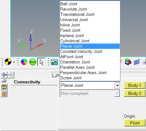
The Project Browser will filter the entities and display only the joints in the model.
The corresponding panel is automatically displayed.
Joints panel - Connectivity tab - joint type drop-down menu |
The model containing the Planar joint can be saved in MDL format from MotionView and exported in the MotionSolve XML format.
The Planar joint can be of the following types:
These types of entities can be added to the model using MDL Statements shown below:
To learn how to create a complete model using MDL Statements please refer to tutorial MV-1060: Introduction to MDL. |
The Planar joint when exported to the MotionSolve XML format is defined as a Constraint_Joint statement. Syntax: <Constraint_Joint id = "integer" label = "Name of Joint" type = "JOINT TYPE" i_marker_id = "integer" j_marker_id = "integer" /> In case of the Planar joint the model statement will be as shown below: <Constraint_Joint id = "301001" label = "Planar Joint" type = "Planar" i_marker_id = "30103050" j_marker_id = "30101050" /> In the above XML Model statement the i_marker_id and j_marker_id represent the I and J markers of the joint which belong to Body 1 and Body 2 respectively. To understand the complete syntax of the Constraint_Joint XML model statement, please refer to the MotionSolve Reference Guide Page for Constraint_Joint. |
In MotionView, the Tcl command layer can be used to add any MDL entities to the model. There are two Tcl commands that can be used to add an entity:
Syntax: mdlmodel_handle InterpretEntity new_handle keyword varname label In case of the Planar joint the statement will look as shown below: mdlmodel_handle InterpretEntity PlanarJt_handle PlanarJoint j_Planar "\"Planar Joint\"" b_1 B_Ground p_ori "NORMAL" "VECTOR" "V_Global_Z" "ALLOW_COMPLIANCE"; |
*This command is not applicable for Planar joint entities. |
The InterpretEntity command is used to add entities to the model and the InterpretSet command is used to set the entity properties (which is not applicable for this type of joint). Extended definitions for InterpretEntity and InterpretSet can be found in the HyperWorks Desktop Reference Guide.
Note - When using the InterpretEntity and InterpretSet commands, it is important to also use the Evaluate command in order for the changes to take effect immediately.
To learn how to create a complete model using Tcl commands, please refer to tutorial MV-1040: Model Building Using Tcl.
The example file below shows a Planar joint connecting two bodies:
*BeginMDL( the_model, "Model", "12.0hwdesktop.110" ) *StandardInclude(FILE) *Point( p_0, "Single Joint Origin" ) *PointPair( p_1, "Pair Joint Origin" ) *Body( b_0, "Single Body 1", p_0, , , , ) *BodyPair( b_1, "Pair Body 1", p_1, , , , ) //Planar joint definition *PlanarJoint( j_Planarjsingle, "Planar Joint Single", b_0, B_Ground, p_0, INPLANE, VECTOR, V_Global_X, VECTOR, V_Global_Y ) //Planar joint pair definition *PlanarJointPair( j_Planarjpair, "Planar Joint pair", b_1, B_Ground, p_1, NORMAL, VECTOR, V_Global_Z ) *SetPoint( p_1, LEFT, , -100 ) *EndMDL() |
See Also:
*PlanarJoint() - Planar joint (normal) (MDL Model Statement)
*PlanarJoint() - Planar joint (plane) (MDL Model Statement)
*PlanarJointPair() - Planar joints (normal) (MDL Model Statement)
*PlanarJointPair() - Planar joints (plane (MDL Model Statement)
Constraint_Joint (XML Command)
InterpretEntity (Tcl Command)
InterpretSet (Tcl Command)