Implicit graphics can be displayed for all applicable entities, allowing you to visualize their location and orientation. Visualization helps you control which implicit graphics are active, as well as size entities and select whether the entity is sized relative to the model or relative to the screen. You can also control the color of each entity.
From the Model menu, click Implicit Graphics to display the Implicit Graphics Settings dialog.
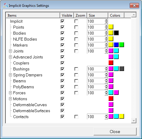
Implicit Graphics Settings dialog
Entities containing implicit graphics include:
| 1. | From the MotionView Model menu, click Implicit Graphics. |
The Implicit Graphics Settings dialog is displayed.
| 2. | Activate the check boxes in the Visible column for the implicit graphics that you want to display. |
| 3. | Activate the check boxes in the Zoom column for the implicit graphics that you want to change size in a zoom,  . . |
| 4. | Enter a value in the Size text box to change the size of a specific implicit graphic. |
| 5. | Click on a color box for the implicit graphic that you want to change color. |
| - | Select a new color or material for the implicit graphic. |
| - | Click OK to the Colors/Materials dialog. |
| 6. | Click Close to close the Implicit Graphics Settings dialog. |
|
See Also:
Graphics Panel


